You just finished a car or truck alignment or other repair that might have disconnected power to the vehicle. You pulled the vehicle off the lift and parked it in the lot. The customer pulls away and, within five minutes, they are back complaining an ABS, stability control or ADAS light is illuminated or a warning message is displayed. What happened?
When you scan for codes, you will find codes C1306, C1307 or another proprietary DTC indicating a malfunction with the steering angle sensor. Depending on the vehicle, these codes indicate a malfunction, inability to find the center or end stops, or missing calibration of the steering angle sensor.
Ninety percent of the time when a steering angle sensor code is active, it means the sensor needs to be calibrated. The other 10% of the time, the sensor has failed or there is an issue with the communication network sharing the data from the sensors.
The calibration process typically involves learning the center and end stops of the steering rack. Some systems require a static calibration in a bay with a scan tool attached. Others require a dynamic calibration which might need to be initiated with a scan tool. Other systems will perform the calibration automatically after a drive cycle.
If the calibration process can’t be completed, it will set a code for the steering angle sensor. Some proprietary codes will indicate why it aborted a steering angle sensor reset. If a code is not active, look at the datastream PIDs to see if the data changes when the steering wheel is moved.
If you are looking for the steering angle sensor data, it could be in several modules. Conventional systems connect the steering angle sensor to the ABS module, which is connected to a high-speed network like CAN. Vehicles with electric power steering typically have the sensors connected to the steering module that communicates with the engine control module to ensure engine speed does not drop when the driver turns the wheel. The steering module is connected to a CAN bus with the ABS and ECM. Another configuration might be to have a “sensor cluster” that communicates on the CAN network on its own.
The steering angle on your scan tool might be in degrees, but on some vehicles it could be a numerical value. Check the service information for the correct values. Most scan tools will have data from two steering angle sensors. Some vehicles will not use zero as the number for centered. Look at the service information. Also, some vehicles might require calibrating the motor position sensor that is located on the rack.
Engineers use two or three steering angle sensors in the column for redundancy and to double-check data. For some vehicles, the angle will have 180 degrees of difference. Other sensors that reveal data and codes are the yaw and lateral acceleration sensors. Dynamic-calibration vehicles will look at data from these sensors to confirm a change in steering angle results in a change in direction for the vehicle. If the sensor is not working or has active codes, a static or dynamic steering angle recalibration will not be possible.
On some vehicles, the steering sensor cluster is part of a module that may include functions for the turn signals, steering wheel, audio controls and wipers. This module is not a box, but part of the column and might have multiple CAN lines coming out of it. Often, the SAS cluster cannot be replaced on its own, instead requiring replacement of the entire unit.
ADAS CONNECTION
The steering angle is used by many ADAS functions, from blind-spot detection to autonomous driving. If the steering angle sensor is not calibrated, it could lead to the false activation of many ADAS systems. The most annoying malfunction is the false activation of the lane departure system. Even the smallest of errors in the SAS can make the vehicle think the driver is trying to steer into an oncoming lane. Some systems may just shake the seat, while other systems might try to steer the vehicle back into the lane.
One of the first items to be replaced on any Tesla model are the tires. This is due to tire wear from the instant torque of the electric motor. When replacing the tires, you will have to service the TPMS sensors.
Tesla has used Baolong (from 2012 to 2014), Continental (from 2014 to 2020 ) and a proprietary sensor that uses Bluetooth. For 2021, the Model Y started to use a sensor that communicates using Bluetooth protocols. Not much is known about the new system except that the sensors are currently available only through Tesla.
The Baolong TPMS system will not display the pressures on the center display. However, the Continental and Bluetooth systems will display the pressures for the driver. Tesla offers a retrofit kit to convert the Baolong system to a Continental system. The procedure involves replacing a module on the vehicle. Baolong sensors are available on the market, and aftermarket replacements can be programmed for the car.
Like many TPMS systems, the Tesla TPMS system has a built-in feature that automatically detects a new set of wheel sensors. The TPMS sensors can be reset via the vehicle’s touchscreen. The reset function is only possible when the vehicle is on.
Before starting, set the tires to the correct cold tire inflation pressure according to the door placard and tire size. Before servicing the tires, make sure the system is functioning.
Auto Learn
Turn the touchscreen on.
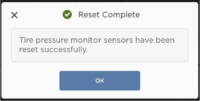
From the touchscreen, touch Controls > Settings > Service & Reset > Tire Pressure Monitor > Reset Sensors. Reset the sensors based on the wheel size. If a tire pressure warning displays, exit the vehicle, close the rear trunk and all the doors, wait for the touchscreen to go black, re-enter the car and ensure that the correct wheel size is selected before touching Reset.
Touch Reset, and then touch OK.
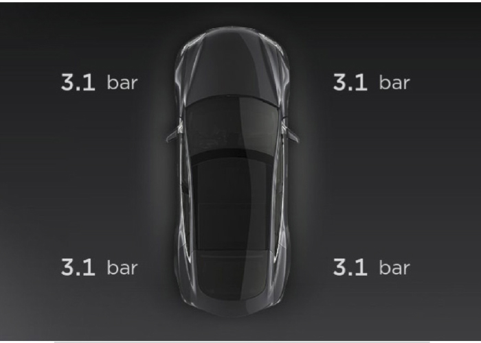
Press and hold one of the scroll wheels and select ‘Car Status’ to see an overview of the TPMS information. When the sensors are unknown, all the values will be shown as “- -”. Ensure that the vehicle is stationary for at least 20 minutes before continuing to the next step.
Perform a road test. Auto learning will start when the vehicle exceeds 25 mph. When auto-learning completes, the tire pressure information displays for all wheels and clears any TPMS faults. Note: Auto learning can take up to 20 minutes during a test drive.
Try this procedure again if “Tire Pressure System Needs Service” displays after performing auto-learning. If the warning still persists after 5 minutes of driving at 25 mph, further diagnostics might be required. This can include using a TPMS to verify the operation of the sensor.
Service Kits
Most Tesla models use service kits that have a clamp-on metal stem. A new service kit should be installed every time the tire is removed from the rim. The valve stem’s nut is a one-time-use item. Most kits are available in two finishes for silver and black rims.
Replacement Sensors
There are a wide variety of programmable 433-megahertz sensors for Tesla models. There are also direct replacement options.
What is up with the foam?
Some original Tesla tires have a layer of foam attached to the inside. This foam is designed to absorb noise from the engine or transmission. If there is a puncture, you can still repair the tire. You can cut the foam away from the area of the tire and use a patch. Just replace the foam section using cement glue.
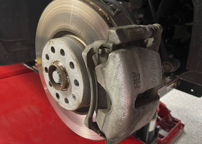
1. Not cleaning the brake slides and hardware: Just slapping new pads and abutment clips where the old ones once resided never works. The caliper bracket slides need to be clean and free from rust. Don’t get overly aggressive with the wire brush. Some automakers are using anti-corrosion coatings and surface treatment on the brake caliper bracket lands. If brake cleaner and a nylon brush can’t tackle the deposits, you might be making the corrosion worse by using a wire wheel or file.
2. Not lubricating the guide pins: This is a shortcut most pad slappers make. Caliper guide pins on floating calipers should always be cleaned in solvent and new grease should be applied. The grease is under extreme heat and pressure, so always use caliper-specific grease. NEVER put a torn boot back on a car. Failure to service the guide pins is the leading source of uneven pad wear. Also, avoid using impacts to remove or install the guide pins. Most guide pins are plated with an anti-corrosion material. Spinning the guide pin in a bore could damage the plating.
3. Installing the brake pads backwards: It happens more often than you would think! You may get a car in your shop with the owner complaining that the brakes are grinding after a “friend” changed the brake pads.
4. Not measuring the rotor: Rotor thickness and runout needs to be measured every time. Running a rotor that is below specifications can cause safety issues like cracking and fading. Also, not correcting lateral runout can lead to a pulsation complaint.
5. Not machining the rotor: New pads almost always require a fresh rotor surface so the pads can deposit a thin layer of friction material to increase braking performance. If old deposits of the previous material are on the rotor, it can contaminate the new pad and lead to performance and noise issues.
6. Not properly torquing the caliper bracket bolts: Not all caliper bracket bolts are the same. Torque ranges can vary from 30 to 110 ft./lbs. Also, some bracket bolts can be torque-to-yield or require liquid tread lockers. If you see an aluminum knuckle, look up the torque specifications.
7. Over torquing the caliper guide pin bolts: Caliper guide pin bolts typically need a 13 mm wrench to remove. It is a rookie mistake to go nuts on these bolts and break the heads off. Typically, these bolts require only 25 to 35 ft./lbs. of torque. Be gentle!
8. Installing a caliper upside down: Nothing is worse than going to bleed a new set of calipers on a vehicle, only to find the bleeders are on the bottom of the caliper and not the top. The bleeder needs to be at the top of the caliper to remove all the air. Always check the box to make sure you have a left and a right before you start the job.
9. Using cheap brake pads: The most common mistake for rookies is to shop for a pad on price and not quality, features and reputation.
10. Hanging the brake caliper by the hose: Nothing is more painful than to watch a brake caliper do a bungee jump from a control arm or knuckle and see it dangle by the brake hose. This can cause damage to the internal structure of the hose, which can cause a soft pedal or a rupture.
The anti-lock braking system (ABS) computer, or HCU, is a node on a high-speed vehicle bus. This means that the information can typically be accessed through the OBD-II DLC.
The ABS controller/modulator is the heart of any ABS or ESC system. The modulator gets the brake pressure from the master cylinder. Located inside are the valves and solenoids that control the pressures to the wheel. During normal operation, the pressure from the master cylinder goes through the HCU unaltered.
ABS is the foundation of the ESC system. ESC systems add software and sensors like yaw, steering angle and even throttle control to keep the vehicle under control.
A basic ABS four-channel system will have eight solenoids (four isolation/four dump), or two for each wheel. Some systems will have more solenoids or valves to isolate the master cylinder from the HCU. ESC systems will typically have 12 or more.
Apply
When the master cylinder applies pressure, it goes directly to the wheel because the outlet/dump solenoid is closed. This is a normal braking event. The unit is in a “passive” state.
Hold
If the system senses a wheel is locked, the inlet/isolation solenoid is closed to prevent any more pressure from the master cylinder from reaching the wheel. The wheel might start to turn.
Release
If the wheel does not start to turn, the outlet/dump valve will open. This will release or bleed off the hydraulic pressure that is holding the wheel. The wheel will now rotate.
Reapply
Since pressure from the master cylinder has been bled off, the pump in the HCU will spool up and apply pressure. The outlet valve is closed and the inlet valve is opened. The pump applies pressure to the wheel.
If the wheel is still outside the wheel slip parameters, the cycle will start over. This happens very quickly.
On older systems, the operation of the solenoids and pump will cause a “kick back” or pulsation in the pedal. Modern systems are able to minimize the kick back through valves that isolate the master cylinder from the HCU.
HCU Mechanical Problems
Mechanical issues with the HCU are rare, but they can occur. Valve seats and pintles can become stuck or not seat properly due to debris, corrosion or contaminated brake fluid.
If the inlet/isolation valve is stuck open, it will not affect normal braking in any way. It will hurt only the ABS system. This could lead to a pulling condition during ABS activation.
If an outlet/dump valve is stuck open in one circuit, this could cause a pull condition during normal braking. This is due to the loss of brake pressure at a wheel. Typically, this is not discovered until brake hoses, calipers and other parts have been replaced.
Testing Solenoids Electrically
Sometimes a stuck or defective solenoid or pump will set a code. A solenoid has a resistance between 2 and 8 ohms. On some units, it is impossible to access the individual solenoids. Testing the unit with a scan tool with bidirectional control might be the best way to confirm the condition of the HCU.
Most vehicles equipped with ESC will have 12 valves or solenoids in the HCU. Eight solenoids control the wheels. Four additional solenoids can block off the master cylinder and allow the pump to send pressure to a specific wheel.
Understeer is a condition where the wheels are turned, but the vehicle continues to travel in a straight line. This is sometimes described as a push.
The ESC computer would see this event through the sensors. The wheel speed sensors in the front typically read slower than in the rear. The computer also would see that the steering angle is greater than the intended path.
The ESC system needs to intervene before the event occurs, and it needs to anticipate the problem and correct it as the vehicle travels.
This is what the ESC sees during an understeer event. The SAS angle is at +52º, which means that the customer has the wheel turned to the right at a significant angle. Even with the steering wheel turned, the yaw and accelerometer read like the vehicle is going straight. The APPS, or accelerator pedal position sensor, shows the driver is off the gas and the brake pedal is not pressed.
The deciding information for the system is in the wheel speed sensor inputs. There is a 6 to 9 mph difference between the front and rear speeds. The front wheels are traveling slower than the rears.
Why Brake Lines Fail During Winter
Winter is when the ABS HCU has to do the most work to make sure the tires have traction during braking and acceleration. When the ABS activates, the pulsing of pressure can create a hydraulic jackhammer. If a line is weak due to internal or external corrosion, it will cause the line to rupture and leak.
Rock salt and deicing brines can corrode brake lines. Automakers have tried galvanization, polymer coatings and physical barriers to stop this corrosion, but these surfaces can’t prevent age and the pecking of road debris from causing corrosion. A hydraulic brake system is only as strong as its weakest connection. Splicing together corroded line does not work in most cases, and replacing just the leaking section will result in a comeback. The best practice is to replace the hard line from the wheel well with an undamaged line. On vehicles with coated line, you must find the area where the coating is still intact.
Another factor influencing brake line replacement is how modern cars are manufactured. In most cases, the brake lines are installed on the unibody, and the subframes for the suspension are fastened to mounting points. Most of these lines are one piece and will go from the HCU or subframe connector to the caliper.
Installing a pre-bent line might be cost prohibitive for the customer because major disassembly is required. One option is to use tubing that can be formed in place. Or, pre-bent tubing can be cut into sections so it can be maneuvered into place without having to remove the subframe. The placement of brake lines is not coincidental.
With ABS-equipped brakes, never take a flare for granted. To seal brake lines against 2,000 psi takes some geometry. The male and female surfaces of the fitting are three to five degrees different between the sealing surfaces. In some cases, the flare is designed to crush or compress onto the surface to form a seal, and the tolerances can stack up quickly against you. An off-center cut combined with a poorly clamped line may look fine to the naked eye, but the connection may leak when it is compressed by the fitting.
If you install new brake lines on a modern ABS-equipped vehicle, you will need a scan tool to bleed the brakes. Air bubbles in the system can occur in the modulator body if the system has lost all of its brake fluid. Removing these bubbles may require the use of a scan tool to open up the isolation and the dump valves in the modulator.
New vehicle ADAS and autonomous features all rely on the alignment being exactly as it should by OEM specifications for the driver-assist features to perform correctly.
Vehicle alignment has always been a critical piece to the repair and safe operation of any vehicle. In years gone by, we all experienced a customer who would return after repairs were completed with concerns about the vehicle pulling or not staying in the center of the road. Although it happened, it was not all that common because any issues that would affect the alignment were usually found during the repairs.
Today’s vehicles shine a whole new light on how important a vehicle’s alignment is. The new advanced driver-assistance systems (ADAS) and autonomous features on vehicles all rely on that alignment being exactly as it should by original equipment manufacturer (OEM) specifications for the driver-assist features to perform correctly. It is not just about going straight down the road anymore; now, the vehicle’s attitude or alignment to the roadway is also a factor.
Is an Alignment Needed?
This brings to light what to do if the repairs do not warrant an alignment. Think about this scenario: A car is traveling across a parking lot at a low rate of speed. A collision occurs with a pickup truck that causes light damage to the front bumper cover and grille. In that bumper cover behind the grille is the radar for the adaptive cruise control. The bracket that holds the radar is bent, requiring replacement.
Let’s assume all other aspects of the bumper cover are repairable, according to OEM parameters. Following all of the OEM repair procedures, it’s noted that a calibration of the radar is required due to the bracket being replaced – which required the radar to be disconnected, removed and installed (R&I).
The shop reads through the OEM prerequisites to do the calibration for the vehicle. These include (depending on the vehicle manufacturer):
Fill the fuel tank to full;
Fill all fluid levels;
Correct air pressure;
Have the proper tires and wheels for model of vehicle;
Verify the alignment;
Verify the steering wheel angle sensor is correct.
There is more I can add, but you get the point that there are required preparations of the vehicle prior to doing a calibration. Also, to do the static calibration, there are environmental requirements, such as level floor or – for dynamic calibrations – weather conditions.
During the calibration, a drive cycle is performed to verify that all systems are operational and it’s found that the vehicle is out of alignment and the calibration fails. The alignment issue is not the result of the damage from the collision that was repaired.
To complete the calibration required for the repairs and procedures that were performed, an alignment must be done. Who’s responsible for the cost of that alignment? It’s a question that’s coming up in many shops across the country. This is not a bent or broken part that’s unrelated prior damage that’s easily pointed out to a vehicle owner; this is a simple condition of the fact that vehicles can be out of alignment just from daily commutes every day.
Another question pops up from the prerequisites: Who pays to fill the tank with gas? Interestingly enough, I’ve asked many shops and insurance companies this question and gotten a lot of different responses. Some said the alignment may or may not be covered, but it was interesting that almost all said “no” to the tank of gas.
Covering the Cost
Let’s look at another scenario: An owner takes a vehicle to a technician because the vehicle is wearing the tires unevenly. It’s found that the vehicle needs an alignment. The parts and labor are the responsibility of the vehicle owner, as this is a general maintenance issue. It’s also found that the vehicle will need to be calibrated, since the alignment changed the vehicle’s attitude to the roadway. Now, the calibration must be added to the repair. The cost of doing the alignment has now increased tremendously for owners of vehicles with ADAS.
We know that the vehicle maintenance of any motor vehicle is a cost the vehicle owner must pay, as no insurance claim is involved. However, we’ve all learned over the years that the lines get muddled when a third party is covering the cost. When a third party is involved, the key phrase “repair to pre-loss condition” is all a party is required to pay. Unrelated prior damage or even maintenance issues on vehicles that have an effect either on the repair itself or the safety of the vehicle have always been a problem in the repair industry. Nobody wants to put a vehicle that is unsafe or dangerous back on the roadway.
High deductibles and procedures not covered by insurance is money many people are having difficulty with. I know this varies from city to city and from different companies or third parties who are paying for the vehicle repairs, but whether it be a bad part, an adjustment to toe or a steering wheel angle sensor procedure, the need for the alignment to be within specifications is more critical than in the past. We, as an industry, need to be prepared to have more conversations about customers paying for alignments and calibrations and their prerequisites. Many shops are adding signage or verbiage to make consumers aware that fuel charges, that the owner will be responsible for, may be added to the costs.
Releasing a vehicle with the safety features compromised or disabled is not an option a shop should pursue. Not following all the guidelines necessary for a proper calibration will bring the shop a whole new level of scrutiny that it will not want if the unfortunate event of a crash occurs.
Let’s say the alignment was not done or verified to be correct and the customer comes back with a drivability complaint. Who is responsible for the costs to complete the alignment now? Remember hearing, “Well, it was not like that before you fixed my car.”
A warranty is never good for any shop, as it costs the shop money to have an alignment done – whether it is in-house or subletted out – and upsets workflow. Add to that the fact that the customer is now not as happy as he or she should be with the vehicle repairs and is spending time getting it corrected. This can have a demoralizing effect on shop management and your team. No technicians want to do repairs or warranties for free, even if it is to make the customer happy.
The Blame Game
Another growing trend is the vehicle’s owner’s manual states that the driver has ultimate responsibility in the operation of the motor vehicle. In today’s new society of “nobody is responsible for anything that happens,” if a vehicle were to be involved in a crash, I can see people wanting to blame the last person who repaired the vehicle’s safety features: “My car did not do what it was supposed to do.” Doing a calibration in the parking lot or not verifying the alignment can make a jury overrule the owner’s manual or side with basic common sense. Even if nobody, such as the third party or customers themselves, will step up to the plate and pay, can you afford to be uncertain whether the vehicle is compromised when it leaves your shop?
Summary
The alignment issue has been a problem for a while now in many aspects of vehicle repair. To verify an alignment, you’re basically required to actually do the alignment.
The good news is new tools are being developed that are capable of doing quick checks on a vehicle’s alignment. This is valuable to all shops doing body work, mechanical or auto glass. Instead of doing an alignment or setting up the vehicle on an alignment rack, these tools can be used right on the level floor of the shop, saving setup time and labor. This will become a big item for the auto glass industry, which currently does not even address the requirements for verifying alignment; the windshield is replaced and possibly calibrated, then out the door it goes. AUTEL, Hunter and Bosch offer systems that do quick checks on alignments for body shops and auto glass replacement companies.
Educating vehicle owners and the public on the processes and procedures to repair vehicles is a must today. Spending time explaining and informing every customer of what it takes today to repair a vehicle is not the same as yesterday … and these conversations may help to ease into who pays for what in the new world of automotive repair.
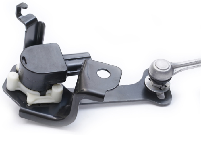
Ride-height sensors not only measure the position of the suspension, but also the rate of movement. They are supplied with a voltage of around 5 volts. The signal voltage is changed as a magnet moves past a coil. Most sensors have three wires — ground, power and signal.
Internally, it is difficult to damage one of these sensors. Externally, the linkage that connects the sensor to the suspension arm can also be damaged. The connector can be damaged and cause a short or open and a code will be set. If one of these sensors is replaced, it must be calibrated after it is installed.
Ride-height sensors are sometimes called suspension-position or wheel-displacement sensors. The data from the sensor is used to measure the movement of the suspension. By knowing how far and fast the suspension is moving, the module can use the information to determine the size of the orifice in the dampener to control compression and rebound.
Measuring Body Movement
Accelerometers are simple devices in theory. Imagine a fishing rod mounted to a moving object like a suspension knuckle. As the object moves, the fishing rod deflects. The faster or farther the object moves, the more deflection there is in the fishing rod. An accelerometer is similar to the fishing rod, but instead of a rod, you have an almost microscopic beam mounted between fixed sensing elements. As the beam moves between the fixed elements, the “capacitance” of a circuit changes.
Accelerometers, however, do not measure distance, but rather movement, inertia and gravitational forces. When mounted to the body of the vehicle, the data can be used to see how the movements of the suspension are influencing the body.
Information from the accelerometers is coupled with data from the ride-height sensor, steering sensor and other inputs by a computer processor in a module. The module can determine if the vehicle is going around a corner or traveling down a bumpy road. With this datastream, the valving inside the dampener can be adjusted in milliseconds for the best control and ride quality.
The accelerometers on the body differ from vehicle to vehicle. Some manufacturers mount the sensors under the headlights and near the taillights. Others mount the accelerometers on the strut towers. More sophisticated systems use more than two accelerometers mounted in various locations.
Control Module
The control module for the electronic dampeners needs more than the movement of the wheels and body to determine the correct settings for the dampeners. The module uses and shares information with the anti-lock braking system, engine control module and instrument cluster. This information is typically shared on the high-speed CAN serial data bus. On some BMW 7 Series models, the information is shared on the fiber-optic Flex Ray bus.
With all this information, the module can do some amazing things with the adjustable dampeners. Problems like nosedive under braking, torque steer and understeer on FWD vehicles can be minimized. If the vehicle has air ride, the volume and pressure inside the air springs can also be tuned along with the valving in the dampeners to optimize ride quality and control.
BMW M models with a grey-cast friction ring in a floating arrangement that is connected by pins to the aluminum rotor hat.
The customer’s complaints may include:
Visible cracks in the brake discs can be noticed through the wheel opening or during service.
There are temporary vibrations or steering wheel torsional vibrations during braking.
After high brake loads, running noises can be heard when applying the brakes.
Visible cracks are caused by high thermal stresses during rapid heating and cooling of the brake discs. Braking from high speed with cold brake components (less than 212 degrees F) increases the likelihood of cracks to form. These hairline surface cracks are usually spread over the entire brake disc friction area, and have no negative influence on the durability or braking performance. The rotors should not be replaced only for their appearance reasons.
When performing routine service on the brake system (pad replacement due to wear), the brake discs should be replaced if surface cracks are found to be greater than 13 mm, or if the brake disc thickness is below the minimum thickness.
Always replace brake discs in pairs (per axle). Install new brake pads when replacing discs. By doing this, the service life of the friction pad surface is increased, and an even material loss is ensured. Vibrations and/or steering wheel torsional vibrations during braking are caused by applying the brakes on discs with minimal to heavy corrosion. These vibrations are most noticeable when braking from high speeds with cold brake components (less than 212 degrees F), and will diminish with normal everyday operation. Parts replacement is not required.
After high brake loads, running noises can be heard when applying the brakes, and may also be heard to a limited extent after the brakes are released (See the note in the Owner’s Manual).
These noises are reduced during normal everyday operation, due to further erosion of the brake pad friction lining.
Visible surface cracks or crater-like recesses on the brake pad surface are caused by a minor difference in the material of the pad lining, which will decrease with further operation and should not be replaced due to their appearance.
The Aftermarket Auto Parts Alliance, Inc Board of Directors has promoted JC Washbish to Chief Executive Officer, effective January 1, 2025. This appointment follows JCâs promotion to President in early 2024. JC will now serve in his capacity as both President and CEO.
âWe continue to be impressed with JCâs leadership, passion and drive, and we expect the same as President and CEO of the Alliance,â said Eli N. Futerman, Chairman of the Alliance Board of Directors and co-owner of Hahn Automotive Warehouse, Inc. âJC brings a strong vision and direction to our shareholder membership.â
Todd Leimenstoll, Alliance Board Director and Secretary, as well as President & CEO of the Auto-Wares Group of Companies, also expressed confidence in JCâs leadership: âAs a group, we continue to look toward the future and strongly believe in our industry partnerships. JC has proven to be a strong leader, facilitating industry collaboration, and is a forward thinker on how we can all work together to support the entire distribution channel.â
In his new role as President & CEO, Washbish will continue to collaborate closely with all of the Allianceâs shareholders and channel partners to drive business development and strengthen industry relations. All Alliance executive leadership teamsâincluding those in information technology, sales and marketing, category management, and financeâwill continue to report to JC as he leads the Alliance toward achieving its strategic goals.
“The Alliance remains the premier independent distribution program group,” said JC Washbish. “We are committed to fostering growth and innovation, expanding our reach, and continuing to provide exceptional value to our shareholders, channel partners and customers. We have a talented, motivated team driven by our motto: âService is the difference, we get it!â”
JC Washbish joined the Alliance in 2016 as Sales, Marketing, and Brand Manager, with responsibilities that included advertising, promotions, and sales support. In 2017, he was promoted to Director of Marketing, and in 2019, to Vice President of Sales and Marketing. During this time, he played a key role in expanding the company’s marketing and sales initiatives. In 2024, JC was promoted to President, a role in which he helped shape the company’s strategic direction and growth. His leadership experience spans areas such as business development, strategic planning, and team coordination across sales, marketing, category management, and operations.
JC holds a Juris Doctor from Ave Maria School of Law in Naples, Florida, and a Bachelor of Arts in History from Franciscan University of Steubenville, Ohio. He has earned his AAP designation from the University of the Aftermarket and is a graduate of Leadership 2.0, reflecting his commitment to professional development and industry leadership. JC is also the 2024 recipient of the Northwood University Automotive Aftermarket Education Award.
âJC continues to provide strong leadership to the Alliance and its shareholders,â said Corey Bartlett, Treasurer of the Alliance Board of Directors and CEO of APH, Inc. âThe Board is excited about the Allianceâs future, and we are in great hands with JC as President and CEO.â
JC becomes the third CEO in the history of the Alliance, following his father, John R. Washbish, who served from 2010 to 2024, and Richard âDickâ Morgan, who led the Alliance for over 14 years from 1994 to 2009. John R. Washbish will continue to serve the Alliance and its shareholders in an advisory capacity.
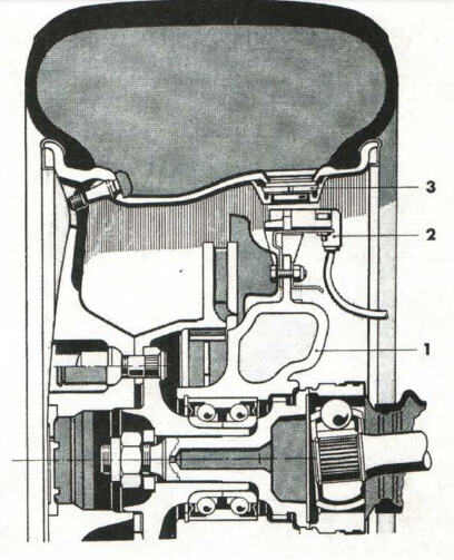
The 959 was another first to use a tire pressure monitoring system (TPMS) because it was equipped with the world’s first self-supporting run-flat tires made by Bridgestone. This TPMS setup was again used on the 928 for model years 1990 to 1994.
The early system used two sensors mounted 180 degrees apart in special holes in the valley of the wheel. The sensors looked like a stack of poker chips. A diaphragm inside the sensors connected to switches that were set to a reference pressure. The receiver was mounted on the knuckle and was an inductive coil that would pass current through the sensors. Depending on the position of the diaphragm and which switches were open or closed, the amount of current flowing through the receiver’s coil would change.
The disadvantage with this early tire pressure monitoring system is the wheels had to have a large hole for the barrel of the wheel for the sensor. Also, the inductive sensor mounted to the knuckle could easily be damaged by road debris.
In 2004, Porsche started to use a conventional TPMS system for the Cayenne and select Boxster and 911 models. These systems were a lot like those found on BMW, Mercedes-Benz and Audi vehicles. The best way to tell if a Porsche has TPMS is to look for metal valve stems. Sensors can last up to 10 years and up to 100,000 miles. But, the life of the sensor can change depending on the tire pressure sampling frequency and temperature extremes.
Many Porsche models have eliminated the spare tire for weight savings. In place of the spare is an inflation pump that can inject sealant into the tire to seal a puncture. The sealant is designed to be compatible with the sensors and should not clog the pressure port on the body of the sensor. The sealant canister has a limited life. Check the service schedule for the replacement interval of the sealant. The typical interval for replacement is three or four years.
Diagnostics
Porsche TPMS systems use four antennas mounted in the wheel wells and a designated module for the tire pressure. The sensors use a 433mHz and 315mHz frequency. On most models, the menu will have the option for two sets of tires and sensor IDs for summer and winter tires.
You can read the remaining lifespan of the battery capacity of the TPMS sensor using some TPMS tools. The value you read out gives an indication if a sensor needs to be replaced.
The system has a telltale malfunction indicator light and a low-pressure light. When the system detects a malfunction, the telltale light will flash for approximately one minute, and will then remain continuously illuminated. This sequence will continue upon subsequent vehicle startups, as long as the malfunction exists.
If a sensor is not transmitting, the warning light in the speedometer flashes for one minute, and then remains continuously illuminated. Codes and data from the TPMS control module can be accessed with a TPMS or scan tool. If there is a problem, it is typically communication errors with the four receivers in the wheel wells.
It is also important to remember that the TPMS module starts hunting for sensor signals the second the ignition is turned on. Leaving the ignition in the “on” position when a wheel is removed may cause the information display to say, “Wheel change? Input new TPM settings.” Also, if the second set of wheels is in the vicinity of the vehicle, the same warning could be set.
Relearn Process
Before starting any relearn process, set the tire to the pressure specified in the doorjamb for the cold temperature. The relearn process starts with turning the ignition on, accessing the vehicle’s computer and entering into the tire pressure control menu. On most models, you will need to select the winter or summer set of tires. The system will then start to learn the sensor IDs and positions.
The onboard computer displays the message “TPM is learning.” The process may take 2 to 10 minutes, and the vehicle speed needs to be above 15-16 mph. During this time, the current tire pressures are not available on the display. The tire pressure warning light will remain lit until all wheels have been learned.
Position and pressure information will be displayed as soon as the TPMS system has assigned the wheels identified as belonging to the vehicle and to the correct wheel positions.
If the Porsche you are working on has custom wheels, mounting the valve stem and sensor can be challenging. Most valve stem holes come in a few sizes, with the most common being 0.453 inches and 0.625. For TPMS valve stems, the size of the hole can be larger for some snap-in and clamp-on holes, but the real problem can be the anatomy of some custom wheels. The valve stem areas may not have the correct size and shape, affecting how a TPMS valve stem seals. And, some custom rims can have drop centers, barrels and flanges that don’t match up with the original rim or TPMS sensor. But there are some options to address this.
A constant velocity (CV) axle includes the axle shaft itself, along with the inner and outer CV joints as an assembly. The shaft itself is a rather mundane part, although there is more to them than meets the eye, but I’ll get to that in a little bit.
Perhaps the most interesting part about a CV axle is the joints, but it all seems more significant when we first look into their predecessor, the infamous u-joint. U-joints can handle a lot of torque, but they have a downside in the nature of their operating characteristics.
U-joints are located on the ends of a driveshaft, the most typical configuration on a rear-wheel-drive vehicle, in which the joints are connected to a front and rear yoke. The front yoke attaches to the transmission and the rear yoke attaches to rear differential. As the engine moves from the effects of torque and as the suspension of a vehicle travels up and down, the angle of the driveshaft changes.
U-joints transfer the motion between the yoke and driveshaft at different angles, allowing for driveline movement. When a yoke and the driveshaft are in perfect alignment, the velocity from one is transferred to the other at the same rate. However, when there is an angle between the two, the velocity of the driven member fluctuates continuously during rotation.
It can be hard to visualize, but the reason this happens is that as the angle of the u-joint changes, the two halves of the u-joint cross are forced to rotate on a different axis. The drive axis remains at a constant velocity, and both ends of the u-joint cross rotate in the same consistent circular path.
The driven axis, however, rotates in a path which causes the distance of travel at the outer ends of the u-joint cross to increase or decrease in relation to the consistent points of the drive axis.
This effect results in the continuous fluctuation of velocity between the input and output sides. While the input remains at a consistent speed, the output speeds up and slows down as the points of the driven axis continuously alter between a long and short path of travel.
So, why don’t we feel that on a vehicle with a traditional driveshaft? Because there are two u-joints and the fluctuation on each end balances out, effectively allowing the driveshaft to provide a consistent output speed to the rear differential. The angle of the two joints must be the same, however, and it doesn’t take much wear in one for the angles to differ, and subsequently cause a vibration.
U-joints are known for their propensity to cause vibration, and the other disadvantage they have is the greater the angle of the u-joint, the greater the fluctuation in velocity. Anything over 30 degrees and the fluctuation dramatically increases. Have you ever noticed how jittery an old four-wheel-drive truck feels in the front when the hubs are locked, and you turn a corner? Now you know why.
A Double-Cardan u-joint. It is basically two u-joints side-by side with a common link-yoke in between. This is one of the original concepts for a true constant velocity (CV) joint, and they are often referred to as this. The advantage they have is they offer smoother operation at greater angles, and they are common on four-wheel-drive trucks, and also a common upgrade for lifted trucks where the driveshaft angle is altered considerably.
The drawback to a Double-Cardan joint is they are bulky, and they can still suffer from limitations due to operating angle. True CV joints, as we know them today, have been around since the early 20th century, but the popularity of the front-wheel-drive (FWD) vehicle is what made them a household name.
Today’s CV joints are a radical departure from anything resembling a u-joint, and not only do CV joints transfer power without speed fluctuation, but they also can operate at angles up to and exceeding 50 degrees, depending on the joint. Since the drive wheels on a FWD vehicle also steer, the ability for this increased operating angle is what makes the CV joint so beneficial for FWD.
A FWD vehicle has two CV shafts, one on each side, and each shaft features an outboard and inboard joint. The outboard joints are considered fixed joints, meaning they don’t offer in and out movement. It’s their ability to operate at the increased angles for steering that’s important. The inboard joints are considered plunge joints, meaning they offer a wide range of inner and outer directional movement in order to take up for length differences as the suspension travels up and down.
You’ll see two types of CV joints. One is the Rzeppa design, which features steel balls trapped in a cage and riding on an inner and outer race. The tri-pod design is the second, which features three roller bearings that ride in a race or cage, sometimes referred to as a tulip assembly. Both types of joints can be found in either a fixed or plunging design for outboard or inboard use, but the Rzeppa design has proven more popular as an outboard joint. The Rzeppa works well as an inboard joint too, but the tri-pod design gets the nod for the most effective operation as a plunge joint.
The CV shafts themselves can differ in length from side to side, and in early FWD development, torque steer, the vehicle pulling one direction or the other during acceleration, was sometimes a result of this difference. Different diameter shafts as well as hollow versus solid became part of the design aspects to combat this problem. Drivetrain mounting and torque control has also advanced considerably since the early days of FWD, and torque steer is rarely a problem.
Due to their overall advantages, CV shafts are now utilized front and rear, and it’s not uncommon to see driveshafts that feature CV joints instead of u-joints. U-joints aren’t forgotten, however, due to their ability to handle high torque and work well in abusive environments that may not be so friendly to the boot on a CV joint (such as the exposed location of a driveshaft under a truck).
CV joints are packed with a specially formulated grease, and a rubber boot is sealed to both the CV shaft and the joint, to keep the grease in place. When a boot is torn or begins to leak, the grease goes away, and dirt gets inside. CV joints typically need no service until this happens.
There was a time when the most common service for a bad boot was to remove the CV joint, take it apart, clean it, repack it and install a new boot. Generally, this was routine, however from time to time you could experience a nightmare. Much of the reason we replaced the boots and serviced the joints in this manner was due to the high cost of a replacement joint or a complete shaft. Even with the additional labor, it was far more cost effective to replace just the boot.
Over time, with advancements in manufacturing and the availability of supplies, the cost of complete CV shafts went down, and it simply made more sense to replace them as a complete unit, not to mention it makes things easier for technicians.
The most important part of selling a new CV shaft is making sure it’s the correct one. You should compare shaft length, the size of the CV joints, and if the vehicle is equipped with antilock brakes with a tone ring on the outer CV joint, be sure the replacement has this ring. Some early CV joints had the tone ring cast into them, but that design was quickly abandoned for a press-fit tone ring. If your customer doesn’t yet have the original shaft out, recommend they make these comparisons prior to installing the new shaft.
Some CV shaft applications come with an ABS tone ring installed, regardless of whether or not the vehicle is equipped with ABS. If not, in most cases, the ring has no consequence, however in the rare situation where it rubs or contacts something, the rings can be removed easily.
The final, and perhaps most important, recommendation is to always torque the fastener that secures the outer CV joint in the wheel hub. If the factory procedure is not adhered to and the correct torque specification not used, damage can and will occur to the wheel bearing.