Archives February 2025

Transmission Fluid Hydraulics


Transmission Fluid Hydraulics and Shifting

To understand why using the correct transmission fluid is necessary, you first have to know how the transmission fluid flows inside an automatic transmission. 

Fluid Paths

The journey starts in the pan. The transmission fluid is drawn from the pan through a filter by the pump that is behind the torque converter. The fluid level in the pan and transmission body is critical. Too little, and the transmission will suck air into the pump. Too much transmission fluid and the fluid will come in contact with the rotating components. Both scenarios lead to aeration of the transmission fluid.

First off, air or bubbles in the transmission fluid can be bad for the performance of the transmission because air can be compressed; fluid can’t be compressed. Air in the system can prevent solenoids, check valves and actuators from engaging clutch packs and bands on the drums. It can even prevent the torque converter from engaging the transmission and shifting the gears. This is basic hydraulics.

The pump first generates a suction force that draws the fluid into the chamber and is eventually compressed on the other side with considerable pressure. Some transmissions might have a second pump in the rear. The pressure created can cause cavitation that can introduce tiny bubbles into the fluid if the formulation is incorrect or the additive package is worn out. 

After the pump comes a valve or valves that do two things. First, it controls line pressure to the valve body and other components. On most transmissions, the line pressure must remain constant as input and output speeds change and as solenoids open and close. To keep the correct line pressure, the fluid must have the correct weight or viscosity.

Second, the pressure regulator valve will direct the fluid to the components like the valve body, torque converter, gears and servos. It will also direct some fluid into a thermostatically controlled cooler circuit. 

For most transmissions, the first stop after the pressure regulator is the torque converter. For the torque converter to work, the stator, turbine and impeller must be submerged in fluid. If air exists inside the body of the torque converter, the fluid can become aerated or foamy, the efficiency of the turbine and impeller is compromised and the vehicle might not move.

On most late-model transmissions, the fluid inside the torque converter lubricates the friction materials and surfaces of the clutch that control lockup. In addition, fluid travels through the turbine and output shaft to lubricate clutch packs, shafts and planetary gears.

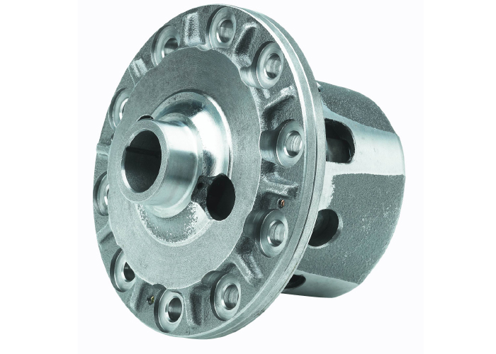
The pressure regulator valve also supplies consistent line pressure to the valve body. The valve body is nothing more than a series of valves, solenoids and accumulators that are connected to servos that engage clutch packs and bands that control that controls the planetary and sun gears of the transmission.

Fluid Conditionals

Hydraulic components need clean fluid that is of the correct viscosity to control the input and output of the transmission. If the fluid is not correct or worn out, it can cause the valves to leak or stick, and cause slipping or even harsh shifts.

Transmission fluid may stay in passages of the valve body and servos and eventually be cycled through relief ports. Some circuits in the turbine and output shaft carry heat away and lubricate friction surfaces. But, it will ultimately end up in the pan, and the fluid will be cycled through the transmission again and again.

Keep in mind, a transmission is a sealed system. What contaminates transmission fluid is high temperatures that oxidize the fluid and break down the raw ingredients. This eventually leads to damage of the components inside the transmission. 

Now that we know the flow of the transmission fluid, we can understand what the fluid is up against inside the case of the transmission. 

There is not a single or universal recipe for automatic transmission fluid. Most fluids use the same type of ingredients, but they are formulated to different specifications depending on the transmission manufacturer.

The transmission fluid is formulated for the friction material used on the clutches, gasket and seal materials, the metallurgy inside the transmission, the length of the service interval, fuel economy requirements, shift quality, and performance at specific temperature ranges.

The engineers at the OEMs and fluid formulators have many ingredients to choose from to achieve the desired performance. 

By volume, the number one ingredient is the “base stock.” This is a highly refined mineral oil classified as a synthetic fluid. The base stock is formulated for performance under high and low temperatures, shear strength and other lubricating properties. It represents 80 to 90 percent of the volume of the fluid.

The viscosity specification of the base stock is going lower on the latest transmissions to improve the pump’s efficiency. This is why you see transmission fluid bottles and specifications with “LV” or low viscosity in their names.

Additive Packages

The other ingredients in transmission fluids represent its additive package. These chemical ingredients help to give the transmission fluid the ability to operate and protect the transmission. 

By volume, detergents are the next largest ingredient in transmission fluid. Detergents help keep surfaces clean from varnish, an advanced form of sludge, and act as dispersants to control contamination and sludge. 

When transmission fluid is exposed to extreme temperatures, the long chemical chains of the hydrocarbon base stock are damaged when they bond with oxygen. So, instead of a nice long chain, they look like balls of wadded-up molecules that can be very sticky. These oxidized molecules like to stick together because they are electrically charged. As more fluid is oxidized, more of them can stick together and form sludge and varnish.

Detergents and dispersants surround oxidized particles and prevent them from linking up and forming sludge and varnish. The contamination remains suspended in a solution with a protective layer around it. 

To prevent the transmission fluid from oxidizing, transmission fluids will include antioxidants. These chemicals enhance thermal stability, improve lubricant performance and reduce sludge formation. They also minimize fluid thickening and control acid formation.

Fluid and Friction

Friction modifiers control the friction levels between the components of the clutches and bands. These ingredients can be tuned to give the best shift performance and extend the longevity of the friction materials.

Anti-wear ingredients are designed to reduce wear between the metal parts that are under extreme pressure. These chemicals help improve the lubricity of the fluid, so it sticks to a metal surface.

Another part of the additive package are anti-foaming ingredients that prevent bubbles from forming in the fluid. Bubbles can be formed due to cavitation in the pump, torque converter and the actuation of the valves since air is compressible. Foamy fluid can change shift characteristics and the hydraulic operation of the transmission.

There are also buffers that control the pH of the fluid. They help to reduce corrosion inside the transmission.

The base stock and additive package must be compatible with the metals, gaskets and seals inside the transmission. Some transmission fluids even include seal conditioners to keep gaskets and seals flexible.

The additive package components do degrade or become depleted over time and need to be replaced by installing fresh transmission fluid. In other words, the chemicals that control the pH friction levels and prevent sludging have a limited supply. When these ingredients are exhausted, their control over the characteristics of the fluid quickly changes.


Automotive

ADAS False and Failed Corrections


Most ADAS system features and their performance are a mystery to the vehicle’s owner and even the dealership. Often a normal activation of the system is misunderstood, which creates problems for the person trying to address a customer complaint. But, what can be worse is trying to figure out why an ADAS feature did not activate.

With today’s modern ADAS systems it can be difficult to determine what is normal and what is a false activation from just a customer complaint. Over the past two decades, ABS, ESC and ADAS have changed the driving experience. When an average driver started driving, they had brake and chassis systems that alerted drivers to potential safety risks with mechanical cues like locking brakes, oversteer and understeer. The first significant change came with ABS. If you were working 25 years ago, you would expect to get customers complaining about sinking and pulsating brake pedals on the first snow of the year.   

Many of these complaints are routine operations for the system. But, there is always the possibility of a false activation of these systems when a correction is not required. Diagnosing false activation of a safety system like ABS or automatic emergency braking (AEB) can be difficult due to the intermittent nature of the complaint. Many false activation scenarios focused on a single malfunctioning sensor, but with ADAS, the cause of false activation of a feature could be more mechanically holistic.

One of the first false activation complaints was ABS activation at speeds between 3 and 15 mph. This problem usually starts with the wheel speed sensors. A weak signal from a sensor is interpreted as a locked wheel, which triggers the computer to activate the ABS and release brake pressure to unlock the wheel. The driver might experience a longer-than-normal stop. The cure for false activation is to clean the tip of the wheel speed sensor, inspect the tone ring and adjust the air gap. This typically fixes the problem.

New magneto-resistive or “active” wheel speed sensors are not prone to issues of metal accumulation on the tip of the sensor. However, debris can build up on the magnets embedded in the reluctor ring in the outer seal of some sensors. This can take a long time to accumulate.

False activations are still a problem with active sensors, but more advanced modules can determine if a wheel is locked or has a wheel speed sensor problem. Instead of activating the ABS module and causing long stops, the system will deactivate and the ABS warning light will turn on.

ESC FALSE-ACTIVATIONS

The next false-activation scenario involves the ESC system. The source of the problem can be more than one sensor and can even be traced to alignment angles. The customer may overlook an issue until there is a mechanical problem with the brakes. In these cases, you may notice that one wheel is covered in brake dust. Some customers may complain that the ESC activates on slower corners or on highway off-ramps.

The most important sensor is the steering angle sensor, which measures the steering angle, steering wheel speed and torque the driver applies. This input tells the ESC system what the driver wants to do. The other sensors tell the ESC system what the vehicle is doing.

Let’s examine what happens during an understeer condition where the wheel turns, but the vehicle travels in a straight line. The driver will continue increasing the steering angle, but the lack of traction keeps the vehicle straight.

The ESC computer sees the understeer event via the sensors long before the driver realizes it. The ESC computer also sees that the driver’s steering angle is greater than the actual path measured by the yaw and lateral accelerometers.

The ESC system intervenes to make the vehicle turn using the brakes. The first action might be to close the throttle to transfer weight to the front so the tires can gain traction. The next action might be to increase braking force on the inside front and/or outside rear tire to get the vehicle to rotate. All this time, the sensors are monitoring what the driver is doing and the effectiveness of the correction. This happens in nanoseconds.

Let’s say a steering position sensor gives a false reading of an extra 50° when the car travels in a straight line. The ESC might perform a correction by activating the brakes to get the steering angle to match what the other sensors are seeing.

The other possibility is the extra 50° on an off-ramp may trigger the ESC system because it is interpreting the signals as an understeer condition.

Another false activation scenario can be caused by an excessive thrust angle. The thrust angle is an imaginary line drawn perpendicular to the rear axle’s centerline. It compares the direction the rear axle is aimed at with the vehicle’s centerline. Excessive thrust angle can cause the vehicle to go down the road at an angle with the steering wheel turned to one side.

The ESC system can experience the effects of an excessive thrust angle but can’t see the thrust angle. The yaw sensor shows that the vehicle is not traveling in a straight line, and the accelerometers and the steering angle indicate that the driver might be trying to correct it. The accelerometers tell the system that nothing is happening.

The ESC system might read this as the rear end starting to step out, which could be interpreted as an oversteer. The ESC system might try to correct the condition by pulsing the inside rear brake.

ADAS False Activations

ABS and ESC systems are essentially blind. They can sense what is occurring with vehicle dynamics and interpret the driver’s inputs. ADAS systems can sense what is happening outside the vehicle, like lane markings and other objects around the vehicle. ADAS does this using cameras, lasers and radar. The three systems control the vehicle’s dynamics and calculate an effective correction for the circumstances and environment.

False activations can range from the automatic braking system stopping a vehicle when pulling out of a garage, to activating a lane-keeping system when the customer does not expect a warning or even steering correction. The secret to resolving these complaints is to treat them like a drivability problem with a condition, cause and correction.

The condition caused by an ADAS activation might be completely normal. The correction might be a warning or the activation of the brakes or steering. The key to understanding the condition is to know the criteria for activation of the system. 

Many ADAS functions and corrections operate with a similar strategy as an emissions monitor. Like an oxygen sensor or misfire monitor, specific criteria and number of events must be met for the system to activate. 

The other keys to know are the ADAS outputs during a dangerous situation. For some early systems, it was just an audio or visual alert. Some newer systems will shake the driver’s seat to alert the driver. More advanced systems can build up brake pressure and apply the brakes if a collision is imminent. Some systems will take further steps with the steering and even close the windows.

Many ADAS features do not become active until the vehicle reaches a specific speed. Depending on the OEM, pre-collision systems might start working between 5 and 10 mph. Lane departure might not begin to work until the vehicle is traveling above 25 mph. The takeaway from this is that a test drive is required after calibration is performed. Simply pulling out of the bay and parking the vehicle in a spot will not allow the vehicle to activate or run a self-diagnosis routine. Knowing the speed range limits of these systems is critical if you try to perform a dynamic calibration on the road.

The logic behind most ADAS warnings or corrections is to examine the plausibility of the situation. For example, if the camera classifies an object as another vehicle, it will also use the radar sensor to confirm the vehicle’s path. If only one sensor detects an object, it might just decide the camera has made a false identification, and the plausibility that it is another vehicle is low.

Before you start a calibration procedure, you need to prepare the vehicle. Missing a step can cause the calibration process to be aborted or calibration to be off. Also be aware that something as simple as a weak battery can cause problems.

Inspecting the sensors and the vehicle for damage is the first step. Damage to the short- and long-range sensor behind the bumper covers or front air dam might not be seen during the initial inspection, but minor collisions can disturb the sensor and damage the mounting points. It could be from hitting a snowbank or parking block.

You might have to remove the bumper cover to inspect the sensor. The most common symptom is false or delayed activation of the system. If the front radar sensor is pointed up or down, it might detect another vehicle too late, and the correction might be more severe than expected. If the sensor is pointed too far left, it could think it is oncoming traffic in the vehicle’s path.

The other key inspection point is to look at the dash for any lights or messages. Never assume a check engine light is only for engine issues; many codes indicate a loss of communication with the different modules on the vehicle. ADAS systems communicate with many modules on the vehicle. Any problems with missing data could cause problems for ADAS calibrations. If the light is on, pull all the codes from the modules.

An alignment should also be performed to ensure the thrust line is within specifications. The steering angle sensor should also be reset as part of the alignment. Failing to reset the sensor might cause a steering pull and issues with the electric power steering system. It could also make the vehicle think a vehicle in the opposing lane is coming right at them. On some vehicles, the driver may get a warning or correction.


Automotive

Drilled and Slotted Rotors


A brake rotor absorbs and dissipates the heat energy generated by friction. How well the rotor can absorb and then release it into the surrounding air will determine the efficiency and capacity of the brakes.

The design of the rotor determines how it can handle the heat. On vented rotors, the thickness of the plates and how well air flows through the vanes helps to transfer heat to the surrounding air. Curved-vane designs on some vented rotors help to pull air through the center of the rotor to the outer edge and act as a pump. For curved vanes to work, they must be mounted on the hub in the correct direction, just as a directional tire must be mounted on the right wheel.

Slots cut into the face of the rotor have two functions. First, they provide leading edges for a better initial bite from the pad. Second, each groove provides a path for the gases being released by the pad. If the slots fill up with pad material, the brake  system is operating at too high a temperature. Slots are radiused when milled to prevent stress in the rotor. Most slotted rotor manufacturers will not cut the slot to the edges of the rotor; doing so will compromise the strength of the rotor. 

Holes drilled in the rotor can provide another path for the gases to escape from the pads and help with the initial bite of the pad. In some cases, the holes can reduce the weight of the rotor and improve cooling, as well. But there is a science to the holes, so the structure of the rotor is not compromised. Too many holes or holes near vanes can cause cracks. Also, the hole should have a chamfer to avoid creating a stress riser that can cause a crack. 

The size of the brake rotor determines the rotor’s ability to generate brake force or torque. The best analogy is to try to turn a steering wheel using an inner spoke and then again using the outer wheel portion. The farther you move your hand out, the easier it is to turn the wheel.

Two-piece rotors included on some cars and in “big brake” kits have two advantages. First, two-piece rotors reduce rotational and unsprung mass. Second, the hat that is made of aluminum acts as a heat dam to prevent heat from being transferred to the hub, bearings and knuckle.

The most significant trend in rotors is using slots, holes and finishes on the hat and vanes to improve the cosmetics of the brake system. 


Automotive

Correct Components and Calibrations Critical After Collisions


While some of the aspects of Advanced Driver Assistance Systems – or ADAS – still seem like cutting edge technology found only in the world’s most advanced vehicles, the truth is that some of these systems have been around for decades, giving the promise of safer driving experiences to drivers all over the world.

Unfortunately, even though modern vehicles are equipped with increasingly advanced electronic safety systems, traffic fatalities have been on the rise since 2014, and while distracted driving may be a factor, we know that electronic safety systems are not able to offer the benefits they are capable of when vehicles are not maintained.

The performance of electronic safety systems is dependent on more components than you may realize. ABS wheel speed sensors and steering angle sensors provide real-time data that electronic safety systems depend on. ADAS related components like these from Standard are precision engineered and manufactured, and they’re also tested on real vehicles to ensure that they integrate seamlessly with the complex safety systems found in today’s modern cars.

Standard’s Collision Repair Program includes more than 8,000 of the hard-to-find, yet easily damaged parts that collision shops and repair facilities are looking for, including more than 900  ADAS-related components, such as park assist cameras, lane departure system cameras, and advanced sensors like blind spot detection sensors, cruise control, distance sensors, and park assist and steering angle sensors.

It’s the correct integration to the vehicle’s system that is so  critical, so be sure your customers and your technicians understand programming and calibration requirements. For example, components like lane departure system cameras will generally require calibration after an installation but some components such as park assist sensors can just be installed on many vehicles without any programming necessary. So, if an ADAS component doesn’t seem to work correctly initially , it’s unlikely it’s a bad part. If you don’t perform the necessary calibration, the part isn’t defective, the installation was just never correctly completed.

Before replacing any ADAS component, it is important to refer to specific service information for the procedures required for that component.  And before installing any replacement part after a collision, make certain that the mounting surface is true to the original location.

To ensure a complete and timely collision repair, Standard offers a wide range of award-winning in-person, live virtual and online learning classes to better educate technicians. You can do the work for your customer with the right parts and training from Standard.

For more information visit StandardBrand.com.

This video is sponsored by Standard.


Automotive

AWD and ABS Services


Many AWD systems came onto the market in the 1990s. Unlike 4×4 truck systems of the day, these systems were always engaged. Many of the early systems used electro-mechanical ways to manage the distribution of power to the
four wheels. 

Most of these systems used viscous differentials and limited-slip differentials with special fluids inside. These components were prone to failure and are expensive to manufacture. The performance of these systems could also be challenging to control with sensors and actuators.

Around 2004, many manufacturers of AWD systems started to abandon complex transfer case center differentials in favor of less expensive clutches. Many vehicles were no longer equipped with limited-slip differentials. Instead, they were equipped with open differentials. Drivers never noticed the change or felt a loss in off-road or winter road capabilities. So, what happened?

Many of these AWD systems were able to utilize the brakes and sensors in the wheel ends to better control wheel slip. The basic principle is that with an open differential if you lock one side, the power transfers to the other side. 

Transfer case designs were simplified and put the control in the clutches and planetary gears. These changes helped reduce cost while making the system more reliable.

The core controls for most AWD systems are the ABS, traction control and stability control (which uses the ABS brake modulator to control traction). The brake hydraulic control module on these vehicles has at least 12 valves. With these control channels, an AWD with open differentials can perform like it has limited-slip differentials. Passive or open differentials transfer the power to the wheel(s) that is spinning the fastest, or the wheel that is on the ring-gear side of the differential. These systems use the brake calipers to apply pressure to the spinning wheel and send power to the opposite side of the differential. This can evenly distribute the power to the rear or front axles under a variety of conditions.

The corrections are very fast pulsations of the brakes that are undetectable by the driver. If the car or truck is accelerating hard from a stop, the system will apply the brakes independently to prevent slipping. Even if the driver turns off the stability control, the brakes will manage the rear axle, so it performs like a limited-slip differential. If the vehicle is in snow or mud, it can control the traction with the brakes so the differential acts like it is locked.

TORQUE-VECTORING REAR DIFFERENTIALS

The torque-vectoring differentials can control the amount of power going to each wheel connected to the axle. Some high-horsepower FWD vehicles have a basic torque-vectoring differential (like the Ford Fiesta RS) to control torque steer.

Torque-vectoring differentials can work together with the stability control system and PCM to maximize traction during acceleration. It can be used during off-road and on-road situations at a wide range of speeds. The main inputs are the steering position sensor and yaw sensor. The differential control module makes corrections by determining where the driver wants to go and where the vehicle is going to make a correction.

This rear differential can control the power to the rear wheels. These differentials can act like a locking limited-slip or open differential with only a change of the electronically controlled clutches.

Torque-vectoring differentials have another advantage – they can disconnect a drive axle better than any locking hub. Decoupling an axle with clutch packs reduces rotating mass in the driveline and increases fuel mileage. The system will then decouple the center differential. On some vehicles, the driveshaft can be uncoupled from both the transmission and rear/front differential. This decoupling of the driveline can reduce rotating mass and load on the engine. This is all performed in milliseconds, and the driver does not feel even the slightest vibration.

SERVICE AND DIAGNOSTICS

Modern AWD systems need the foundation brake system and wheel bearing hubs with accurate wheel speed sensors to be in proper working order to function. This means that the pads and rotors must be able to produce enough friction to carry out the corrections. Issues with wheel bearings and seized calipers can result in less-than-optimal corrections.

Any leaks from the transmission, transfer case or differential should be taken seriously. Damage can occur if the fluid drops to a critical level. The most common leaks can be found around the driveshaft and axle seals.

Sometimes, there will be oil leakage at the seam between the automatic transmission and the transfer case; it can occur around the entire seam. If droplets can be seen, seal the areas with black sealant in the vicinity of the propeller shaft to the front axle transmission. If the problem is a “sweating” leak, sealing must not be carried out, as this is a normal phenomenon inherent in the design of oil-filled systems. If there are any leaks in the differential transfer case, check the vents and breathers. The seals can leak and fail if the case is over pressurized.

The post AWD and ABS Services appeared first on Brake & Front End.


Automotive

Duramax Diesel Turbo Codes P0290 and P2463


Some turbocharger failures on some GM Duramax 6.6 diesel engines from 2011-2017 are quick and catastrophic. It could start with smoke from the tailpipe or even a catalytic converter clogged with oil and debris. You may notice the engine is down on power. These are easy to diagnose.

Some turbocharger failures for these engines are less dramatic and might not require a replacement unit. Instead, they start with a code and a check engine light. These are typically caught by the engine management system when it senses the turbocharger is no longer producing the expected level of boost for a given engine speed or load.

2017 Duramax 6.6L turbo diesel engine.

No matter the symptoms or damaged parts, the root cause of the failure must be diagnosed and resolved.

The cause of the failure or drivability problem might be related to the oil supply required to lubricate and cool the turbocharger’s bearings. In rare cases, a piece of debris can damage the compressor or the exhaust turbine. The Vane Position Sensor can fail and not command the variable vanes in the turbine housing which control the speed of the turbine. Further to that, this variable geometry turbocharger contain an oil control solenoid that commands vane position, this too can fail and be a fault mode on this unit.

One of the most common codes for the Duramax is DTC P0299. The engine management system knows the expected level of boost pressure for a given condition. DTC P0299 indicates the boost pressure is below expectations. To set a P0299 code it requires multiple incidents over one or two key cycles. If you have a scan tool, you can access the freeze-frame information when code P0299 was set. A P0299 is not an automatic sign the turbocharger needs to be replaced. It is just a starting point for further inspection and diagnostics.

Mechanical failures of a turbocharger are usually related to the lubrication system. For the oil to cool and lubricate the turbo, it must flow. Restrictions in the oil feed or return lines can cause excessive heat along with shaft and bearing wear.

Oil restrictions are typically caused by carbon deposits in the lines and passages. When an engine stops turning, the oil flowing to the turbocharger stops. The oil inside the turbocharger might drain out of the center section through the return line. The remaining oil in the center section is heated to the point where it’s turned into carbon deposits. This process can happen even faster if the driver is using low-quality oil.

When the turbocharger bearings and shaft wear, the seals can leak oil into the turbine and compressor housings. This oil can clog the Diesel Particulate Filter and restrict the flow of exhaust gases. This can cause low boost pressure and a P0299 code.

On the intake side, the air filter may fail due to excessive pressure differential that rips the filter media from the frame. The pressure differential is typically caused by a clogged air filter, so it is cheap insurance to replace the air filter when the turbocharger is replaced and highly recommended.

On the exhaust side, foreign objects can come from anything that can exit the exhaust port. If you deal with an engine failure with catastrophic damage, the turbocharger’s turbine and variable geometry vanes could be damaged.

For all diesel pickups made after 2007, the performance and fit of the turbocharger are critical for the operation of the Diesel Particulate Filter or DPF. In addition, any leaks in the exhaust system from the turbocharger to DPF will lead to codes and problems.

The DPF uses pressure sensors before and after the filter to measure restriction and determine when to perform a regeneration cycle. If the downpipe is leaking, the readings will not be accurate. In some cases, a code P2463 for excessive soot might be active. In other cases, the ECM will not run the regeneration cycle due to the plausibility of the reading from the two sensors. If you encounter one of these leaks, follow the procedures in TSB 15457 to align the downpipe and DPF. The method discussed involves removing the clamps, supporting the exhaust system, installing new gaskets and realigning the pipes.

As an extra quality check, perform a forced DPF regen cycle and check for any resulting codes.

There are several ways to protect a new turbocharger. The lines that supply and return from the oil pan should be replaced if available, or thoroughly flushed and cleaned to guarantee they are free and clear of any blockages inside.  Before the engine is started, the turbocharger should be pre-lubricated with a large syringe in the oil supply line.

The most important thing is to educate the vehicle owner on proper maintenance and oil changes. Most OEMs have specific grades and certifications for vehicles with turbocharged engines. Using the least expensive or what is available at a gas station can damage the turbocharger.

Also, if you encounter a Duramax with a blocked DPF [NS1] [AM2] or damage to the turbocharger due to high temperatures, you might need to educate the vehicle owner on avoiding extended idle times. While older diesel engines might have benefited from letting them idle for an extended period, newer diesel engines could clog the DPF,[NS3]  and the turbocharger might experience higher than average temperatures. Also, the driver may abort the regen process because it is inconvenient, or they fear the higher idle is rough on the engine. The reality is not performing the regen process could damage the new turbocharger.

The bottom line is this: before replacing the turbocharger on a Duramax engine, find the root cause of the failure. By taking the time to do this, you will avoid costly rework.


Automotive

Apakah slot server Thailand lebih sering memberikan free spin

slot server Thailand memang dikenal menawarkan berbagai promosi menarik, termasuk free spin. Namun, apakah mereka “lebih sering” memberikan free spin dibandingkan dengan server lain, itu tergantung pada beberapa faktor, seperti jenis permainan slot, bonus yang ditawarkan oleh situs, dan kebijakan promosi masing-masing.

Mengapa Slot Server Thailand Populer dengan Free Spin?

  1. Banyak Bonus dan Promosi: Banyak situs slot server Thailand yang memberikan bonus menarik, termasuk putaran gratis (free spin), baik untuk pemain baru maupun pemain lama. Ini bisa terjadi melalui:
    • Bonus selamat datang untuk pemain baru yang biasanya mencakup free spin.
    • Promosi mingguan atau bulanan, seperti putaran gratis pada slot tertentu.
    • Putaran gratis sebagai bagian dari fitur game yang diberikan oleh mesin slot (misalnya, fitur scatter atau bonus).
  2. Slot dengan Fitur Free Spin: Banyak slot di server Thailand yang memiliki fitur bonus free spin secara langsung di dalam permainan itu sendiri. Ini berarti bahwa semakin sering Anda bermain, semakin besar peluang Anda untuk memicu fitur tersebut.
  3. RTP dan Volatilitas: Slot dengan RTP (Return to Player) tinggi dan volatilitas rendah cenderung memberikan putaran gratis lebih sering, meskipun nilainya mungkin tidak sebesar pada slot dengan volatilitas tinggi. Beberapa slot di server Thailand memiliki RTP tinggi dan fitur yang memudahkan pemicu free spin.
  4. Keunggulan Promosi untuk Pemain: Beberapa situs Thailand sering kali memberikan promo khusus yang berfokus pada putaran gratis untuk menarik lebih banyak pemain. Misalnya, bonus harian atau event khusus yang menawarkan free spin pada hari tertentu.

Apakah Server Thailand Lebih Sering Memberikan Free Spin Dibandingkan Server Lain?

  • Bergantung pada situs dan jenis permainan: Setiap server, baik itu di Thailand atau negara lain, menawarkan variasi dalam fitur dan promosi. Beberapa server di Thailand mungkin lebih sering memberikan free spin sebagai bagian dari strategi pemasaran mereka untuk menarik pemain, tetapi banyak juga server lain di seluruh dunia yang menawarkan promosi serupa.
  • Strategi Promosi Lokal: Situs slot Thailand sering kali berfokus pada bonus dan promosi yang sesuai dengan kebutuhan pasar lokal mereka, dan ini bisa berarti lebih banyak frequent free spin yang ditawarkan dalam kampanye atau promosi.

Thailand:

Secara keseluruhan, slot server Thailand memang dikenal dengan banyaknya promosi dan free spin yang ditawarkan kepada pemain. Namun, ini juga bergantung pada situs yang Anda pilih dan jenis permainan slot yang Anda mainkan. Jadi, jika Anda mencari slot dengan banyak free spin, carilah situs Thailand yang menawarkan promosi khusus atau permainan dengan fitur free spin yang sering aktif.

Magnets and Drain Plugs

Magnets in transmission pans and oil drain plugs help capture ferrous metals, but how do you know when debris is a sign of trouble? Andrew Markel explains the role of these magnets, what they collect, and how to determine if a transmission or engine issue may be developing. Learn key insights for better maintenance and diagnostics.

This video is sponsored by Auto Value and Bumper to Bumper.

The post Magnets and Drain Plugs appeared first on Brake & Front End.


Automotive

VW Touareg Suspension Issues


The second-generation VW Touareg hit the road in 2011 and finished its production run in 2018. Aligning this Touareg is very similiar to the previous generation. Previous-generation Touareg models had uneven and rapid tire wear problems. The second generation is not known for this issue.

Precautions

The Touareg is not your typical vehicle to align. It has a stability control system that needs a recalibration of the steering angle sensor if the toe front or rear is adjusted. 

On vehicles with air ride systems, lifting the vehicle for a repair requires that the vehicle lift mode must be activated. The vehicle lift mode switches the air suspension control off. This prevents readjusting of the air springs when the vehicle is lifted. Vehicle lift mode is automatically switched off at a speed above 3 mph.

Use the following procedure to deactivate the air suspension:

1. Switch on the electrical parking brake.

2. Switch on the ignition.

3. Press the LOCK button in the center console for 5 seconds.

The “Vehicle Lift Mode” is displayed in the instrument cluster and the indicator lamp in the LOCK button flashes.

Inspect the tires before alignment. According to VW, the tread depth difference may be no more than 2 mm on an axle. Also, the service information says a wheel alignment should not be done until the vehicle has been driven 1,000 to 2,000 km (621 to 1243 miles), since it takes this long for the coil springs to settle. 

Front Suspension

At the front of the Touareg is a double wishbone with a tall knuckle. The suspension can have either air or coil springs. The lower control arm inboard mounts have factory-installed cam bolts to adjust the camber and caster. The front lower cam bolt adjusts camber and the rear bolt adjusts caster.

The most common failure on these models is the lower shock bushing. Upper control arm bolts are torque-to-yield with a torque spec of 50 Nm and a turn of 180 degrees.

Rear Suspension

The rear suspension is a multi-link setup with a large lower control arm. Toe is adjusted with the toe link and camber is adjusted using the cam bolt in the lower control arm. 

If the rear tires have inner edge wear, inspect the bushings for damage. Most likely, the bushing that attaches the knuckle to the lower control arm is damaged.


Automotive

Non-Directional Rotor Finishes


Back in the day, a non-directional rotor finish was the method used to solve a common problem that occurred on bench brake lathes. If the crossfeed speed was too fast, the rotor became like a vinyl record, and the pads became the needle that followed the grooves in the record. This would cause a clicking noise as the pads moved in the caliper as it followed the concentric grooves.

The solution was to apply a non-directional finish. A non-directional finish breaks up the grooves cut by the lathe. These are typically cut with a rotating abrasive disc that moves across the face of the rotor. The finish looks like cross-hatch marks on a honed cylinder. In the 1970s and 1980s, the pages of Brake & Front End had ads for lathes accessories to apply a non-directional finish.

Why was it such a big deal? The reality was that the crossfeed on some lathes was set to what was used for drum brakes. The faster setting made more pronounced concentric grooves on brake rotors. Typically, the solution was to reduce the crossfeed speed to reduce the grooves. Also, many floating caliper designs were not great at holding the brake pads steady in the bracket.

Today, non-directional finishes on new brake rotors still serve the same purpose, but they also help in the bedding of some friction formulations.

The surface finish of a new or resurfaced rotor should meet OEM specifications for good braking performance, pedal feel and quiet operation. Brand-new OEM rotors and aftermarket rotors from a quality supplier typically have a surface finish that can vary from 15 to 80 microinches. Most brake experts say the best finish is 50 microinches or less, though a finish in the 60- to 80-microinch range is acceptable.

When a rotor is turned on a brake lathe with sharp bits (we emphasize the word “sharp” because it is absolutely essential for a quality rotor finish) and a feed rate that is not too fast, the rotors will have a finish that meets these recommendations. Dull bits and fast feed rates tear chunks of metal from the rotor, instead of properly cutting it as they should.

If you turn your rotors with sharp bits and the proper feed rate and depth of cut, using a hone to apply a non-directional finish can help to reduce noise and shorten burnishing times.

As a final step, any rotor should be cleaned so metal debris, oil and anti-corrosion chemicals are removed from the braking surface. Not washing the rotors after they have been turned can leave a lot of junk on the surface that can embed in the pads and possibly cause braking issues, as well as noise when the rotors are installed.

NON-DIRECTIONAL FINISH TECHNIQUES

Non-directional rotor finishes can be applied in a number of ways. One way is by using an abrasive disc in a drill or a special rotor refinishing brush. As with the sanding block, you want to give each side about one minute of sanding while the rotor is rotating on the lathe. Also, follow the manufacturer’s recommendation for rotational speeds. Another method is to hold a pair of sanding blocks wrapped with 120-grit sandpaper firmly against both sides of the rotor for about one minute while it turns on the lathe.

Sanding knocks off the sharp peaks on the surface of the rotor and generally improves the surface finish by 15 to 20.

WHAT REALLY CAUSES NOISE

A non-directional finish can reduce initial break-in noise and help suppress noise for a while; however, brake noise can still occur if there are vibrations between the pads and rotors.

Brake squeal is caused by undampened high-frequency vibrations. When the brakes are applied, and the pads contact the rotors, tiny surface irregularities in the rotors act like speed bumps, causing the pads to jump and skip as they rub against the rotors. If the pads are not dampened by shims (external or internal) or are loose in the caliper mounts, they shake and vibrate and may produce an annoying high-pitched squeal.

The vibration of the pads against the rotors can also create harmonic vibrations in the rotors that cause them to ring like cymbals. Depending on the metallurgy of the rotors and the design of the cooling fins, some rotors may ring louder than others, regardless of the type of surface finish.

So, even if you do everything right, you can still end up with a noise problem if the pads or rotors themselves are inherently noisy. Switching to a different brand of brake pads or substituting a different type of friction material may be necessary to get rid of the noise.

A tip for reducing noise-producing vibrations is to apply a high-temperature brake lubricant to the backs of the pads and the points where the pads contact the caliper. Lubricating the caliper mounts, shims and bushings is also recommended to dampen vibrations here, as the lubricant acts as a cushion. It also helps the parts slide smoothly so the pads wear evenly (uneven pad wear is a classic symptom of a floating caliper that is sticking and not centering itself over the rotor).

The type of rotors used on the vehicle can also affect noise. Some grades of cast iron are quieter than others. That’s one of the reasons why composite rotors have been used on various vehicles over the years. Besides being lighter, composite rotors can also be quieter when the right grade of cast iron is used for the rotor disc. Replacing a composite rotor with a solid cast-iron rotor changes the harmonics and frequency of the brake system and may increase the risk of brake noise on some vehicles. Also, some low-price rotors may use a lower grade of cast iron that is noisier than the OEM rotors they replace.


Automotive