Archives 2025

Porsche TPMS


The 959 was another first to use a tire pressure monitoring system (TPMS) because it was equipped with the world’s first self-supporting run-flat tires made by Bridgestone. This TPMS setup was again used on the 928 for model years 1990 to 1994.

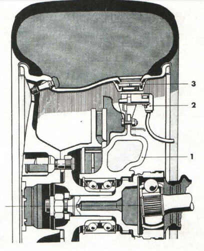
The early system used two sensors mounted 180 degrees apart in special holes in the valley of the wheel. The sensors looked like a stack of poker chips. A diaphragm inside the sensors connected to switches that were set to a reference pressure. The receiver was mounted on the knuckle and was an inductive coil that would pass current through the sensors. Depending on the position of the diaphragm and which switches were open or closed, the amount of current flowing through the receiver’s coil would change.

The disadvantage with this early tire pressure monitoring system is the wheels had to have a large hole for the barrel of the wheel for the sensor. Also, the inductive sensor mounted to the knuckle could easily be damaged by road debris.  

In 2004, Porsche started to use a conventional TPMS system for the Cayenne and select Boxster and 911 models. These systems were a lot like those found on BMW, Mercedes-Benz and Audi vehicles. The best way to tell if a Porsche has TPMS is to look for metal valve stems. Sensors can last up to 10 years and up to 100,000 miles. But, the life of the sensor can change depending on the tire pressure sampling frequency and temperature extremes.

Many Porsche models have eliminated the spare tire for weight savings. In place of the spare is an inflation pump that can inject sealant into the tire to seal a puncture. The sealant is designed to be compatible with the sensors and should not clog the pressure port on the body of the sensor. The sealant canister has a limited life. Check the service schedule for the replacement interval of the sealant. The typical interval for replacement is three or four years. 

Diagnostics

Porsche TPMS systems use four antennas mounted in the wheel wells and a designated module for the tire pressure. The sensors use a 433mHz and 315mHz frequency. On most models, the menu will have the option for two sets of tires and sensor IDs for summer and winter tires.

You can read the remaining lifespan of the battery capacity of the TPMS sensor using some TPMS tools. The value you read out gives an indication if a sensor needs to be replaced.

The system has a telltale malfunction indicator light and a low-pressure light. When the system detects a malfunction, the telltale light will flash for approximately one minute, and will then remain continuously illuminated. This sequence will continue upon subsequent vehicle startups, as long as the malfunction exists.

If a sensor is not transmitting, the warning light in the speedometer flashes for one minute, and then remains continuously illuminated. Codes and data from the TPMS control module can be accessed with a TPMS or scan tool. If there is a problem, it is typically communication errors with the four receivers in the wheel wells.

It is also important to remember that the TPMS module starts hunting for sensor signals the second the ignition is turned on. Leaving the ignition in the “on” position when a wheel is removed may cause the information display to say, “Wheel change? Input new TPM settings.” Also, if the second set of wheels is in the vicinity of the vehicle, the same warning could be set.

Relearn Process

Before starting any relearn process, set the tire to the pressure specified in the doorjamb for the cold temperature. The relearn process starts with turning the ignition on, accessing the vehicle’s computer and entering into the tire pressure control menu. On most models, you will need to select the winter or summer set of tires. The system will then start to learn the sensor IDs and positions.

The onboard computer displays the message “TPM is learning.” The process may take 2 to 10 minutes, and the vehicle speed needs to be above 15-16 mph. During this time, the current tire pressures are not available on the display. The tire pressure warning light will remain lit until all wheels have been learned.

Position and pressure information will be displayed as soon as the TPMS system has assigned the wheels identified as belonging to the vehicle and to the correct wheel positions.

If the Porsche you are working on has custom wheels, mounting the valve stem and sensor can be challenging. Most valve stem holes come in a few sizes, with the most common being 0.453 inches and 0.625. For TPMS valve stems, the size of the hole can be larger for some snap-in and clamp-on holes, but the real problem can be the anatomy of some custom wheels. The valve stem areas may not have the correct size and shape, affecting how a TPMS valve stem seals. And, some custom rims can have drop centers, barrels and flanges that don’t match up with the original rim or TPMS sensor. But there are some options to address this.


Automotive

An In-Depth Look At CV Axles


A constant velocity (CV) axle includes the axle shaft itself, along with the inner and outer CV joints as an assembly. The shaft itself is a rather mundane part, although there is more to them than meets the eye, but I’ll get to that in a little bit.

Perhaps the most interesting part about a CV axle is the joints, but it all seems more significant when we first look into their predecessor, the infamous u-joint. U-joints can handle a lot of torque, but they have a downside in the nature of their operating characteristics.

U-joints are located on the ends of a driveshaft, the most typical configuration on a rear-wheel-drive vehicle, in which the joints are connected to a front and rear yoke. The front yoke attaches to the transmission and the rear yoke attaches to rear differential. As the engine moves from the effects of torque and as the suspension of a vehicle travels up and down, the angle of the driveshaft changes.

U-joints transfer the motion between the yoke and driveshaft at different angles, allowing for driveline movement. When a yoke and the driveshaft are in perfect alignment, the velocity from one is transferred to the other at the same rate. However, when there is an angle between the two, the velocity of the driven member fluctuates continuously during rotation.

It can be hard to visualize, but the reason this happens is that as the angle of the u-joint changes, the two halves of the u-joint cross are forced to rotate on a different axis. The drive axis remains at a constant velocity, and both ends of the u-joint cross rotate in the same consistent circular path.

The driven axis, however, rotates in a path which causes the distance of travel at the outer ends of the u-joint cross to increase or decrease in relation to the consistent points of the drive axis.

This effect results in the continuous fluctuation of velocity between the input and output sides. While the input remains at a consistent speed, the output speeds up and slows down as the points of the driven axis continuously alter between a long and short path of travel.

So, why don’t we feel that on a vehicle with a traditional driveshaft? Because there are two u-joints and the fluctuation on each end balances out, effectively allowing the driveshaft to provide a consistent output speed to the rear differential. The angle of the two joints must be the same, however, and it doesn’t take much wear in one for the angles to differ, and subsequently cause a vibration.

U-joints are known for their propensity to cause vibration, and the other disadvantage they have is the greater the angle of the u-joint, the greater the fluctuation in velocity. Anything over 30 degrees and the fluctuation dramatically increases. Have you ever noticed how jittery an old four-wheel-drive truck feels in the front when the hubs are locked, and you turn a corner? Now you know why.  

A Double-Cardan u-joint. It is basically two u-joints side-by side with a common link-yoke in between. This is one of the original concepts for a true constant velocity (CV) joint, and they are often referred to as this. The advantage they have is they offer smoother operation at greater angles, and they are common on four-wheel-drive trucks, and also a common upgrade for lifted trucks where the driveshaft angle is altered considerably.

The drawback to a Double-Cardan joint is they are bulky, and they can still suffer from limitations due to operating angle. True CV joints, as we know them today, have been around since the early 20th century, but the popularity of the front-wheel-drive (FWD) vehicle is what made them a household name.

Today’s CV joints are a radical departure from anything resembling a u-joint, and not only do CV joints transfer power without speed fluctuation, but they also can operate at angles up to and exceeding 50 degrees, depending on the joint. Since the drive wheels on a FWD vehicle also steer, the ability for this increased operating angle is what makes the CV joint so beneficial for FWD. 

A FWD vehicle has two CV shafts, one on each side, and each shaft features an outboard and inboard joint. The outboard joints are considered fixed joints, meaning they don’t offer in and out movement. It’s their ability to operate at the increased angles for steering that’s important. The inboard joints are considered plunge joints, meaning they offer a wide range of inner and outer directional movement in order to take up for length differences as the suspension travels up and down.

You’ll see two types of CV joints. One is the Rzeppa design, which features steel balls trapped in a cage and riding on an inner and outer race. The tri-pod design is the second, which features three roller bearings that ride in a race or cage, sometimes referred to as a tulip assembly. Both types of joints can be found in either a fixed or plunging design for outboard or inboard use, but the Rzeppa design has proven more popular as an outboard joint. The Rzeppa works well as an inboard joint too, but the tri-pod design gets the nod for the most effective operation as a plunge joint.

The CV shafts themselves can differ in length from side to side, and in early FWD development, torque steer, the vehicle pulling one direction or the other during acceleration, was sometimes a result of this difference. Different diameter shafts as well as hollow versus solid became part of the design aspects to combat this problem. Drivetrain mounting and torque control has also advanced considerably since the early days of FWD, and torque steer is rarely a problem.

Due to their overall advantages, CV shafts are now utilized front and rear, and it’s not uncommon to see driveshafts that feature CV joints instead of u-joints. U-joints aren’t forgotten, however, due to their ability to handle high torque and work well in abusive environments that may not be so friendly to the boot on a CV joint (such as the exposed location of a driveshaft under a truck).  

CV joints are packed with a specially formulated grease, and a rubber boot is sealed to both the CV shaft and the joint, to keep the grease in place. When a boot is torn or begins to leak, the grease goes away, and dirt gets inside. CV joints typically need no service until this happens.

There was a time when the most common service for a bad boot was to remove the CV joint, take it apart, clean it, repack it and install a new boot. Generally, this was routine, however from time to time you could experience a nightmare. Much of the reason we replaced the boots and serviced the joints in this manner was due to the high cost of a replacement joint or a complete shaft. Even with the additional labor, it was far more cost effective to replace just the boot.

Over time, with advancements in manufacturing and the availability of supplies, the cost of complete CV shafts went down, and it simply made more sense to replace them as a complete unit, not to mention it makes things easier for technicians.

The most important part of selling a new CV shaft is making sure it’s the correct one. You should compare shaft length, the size of the CV joints, and if the vehicle is equipped with antilock brakes with a tone ring on the outer CV joint, be sure the replacement has this ring. Some early CV joints had the tone ring cast into them, but that design was quickly abandoned for a press-fit tone ring. If your customer doesn’t yet have the original shaft out, recommend they make these comparisons prior to installing the new shaft.

Some CV shaft applications come with an ABS tone ring installed, regardless of whether or not the vehicle is equipped with ABS. If not, in most cases, the ring has no consequence, however in the rare situation where it rubs or contacts something, the rings can be removed easily.

The final, and perhaps most important, recommendation is to always torque the fastener that secures the outer CV joint in the wheel hub. If the factory procedure is not adhered to and the correct torque specification not used, damage can and will occur to the wheel bearing.


Automotive