PRT announced the launch of 20 new products in North America. The new part numbers include complete strut assemblies and shock absorbers, representing nearly 8 million vehicles in new coverage. The launch includes coverage for light vehicles like the Hyundai Sonata, Mercedes-Benz C-Class and Subaru WRX, in addition to popular pickup truck applications, including the Ford F-150, Chevrolet Silverado and the Dodge Ram 1500, among others, according to PRT.
The technician shortage is no secret, but the solution might be closer than you think. In a recent Tomorrow’s Technician Partnership Pathways podcast, Van Harris, a regional sales rep for NAPA Auto Parts, shared how strong partnerships between schools, shops, and suppliers can help secure the future of the industry.
Harris has been working with automotive training programs for over two decades, helping schools like Chapel Hill High School transform their programs from underfunded afterthoughts into thriving pipelines for skilled technicians. Under the leadership of instructor Robert Ballard, the program has grown from 50 students to over 300, thanks in part to strategic industry support.
Why Should Shop Owners Care?
Harris makes a powerful case: if today’s repair shops don’t invest in technician training, they won’t have a workforce tomorrow. He regularly brings shop owners, dealership representatives, and industry leaders into classrooms to showcase the talent being developed and encourage them to engage with students directly.
Shops that get involved now can: ✅ Build relationships with future techs before they enter the job market. ✅ Help shape training programs to ensure students develop real-world skills. ✅ Create mentorship and apprenticeship opportunities that benefit both students and businesses.
How Can Shop Owners Get Involved?
1️⃣ Join advisory boards – Schools need input from industry professionals to shape their programs. 2️⃣ Offer hands-on training – Loaning tools, donating equipment, or providing shop tours can make a big impact. 3️⃣ Mentor students – Encouraging young talent and offering internships builds a stronger workforce. 4️⃣ Support diversity in the trade – With 33% of students in Ballard’s program being female, now is the time to foster inclusive opportunities.
Harris emphasizes that this isn’t charity—it’s an investment. As he puts it, “If you don’t invest in this, you won’t have a business in 10 to 15 years.”
The Bottom Line
Shops that take an active role in training the next generation will be the ones with the skilled techs needed to stay competitive. If you’re not already working with a local school, now’s the time to start.
Vacuum brake boosters will probably be with us for a long time. It is the most efficient and economical way to amplify the force exerted by the driver. But where the booster gets its vacuum is changing. Many import and domestic nameplates have been using vacuum pumps to power the brake booster on their gas-, diesel- and even electric-powered vehicles.
For a vacuum brake booster to work, it needs a source of vacuum. In the past all that was needed was a port on the intake manifold. Now, vacuum pumps are the choice for negative pressure power.
Why a Vacuum Pump?
In every piston engine, vacuum is generated during the intake stroke as the piston goes down in the cylinder and the intake valves are open. But modern engines have changed. Increased efficiency has reduced the amount of vacuum available to the brake booster. Engines have been downsized to 2.0- and even 1.4-liters. This means that there is less displacement to generate the vacuum.
Variable valve timing has further diminished the vacuum generated because the timing of the opening might be timed to allow a scavenging effect so some of the intake air makes it past the exhaust valve. This air is intended for the catalyst so unburned hydrocarbons can be burned.
Turbocharging has also eliminated traditional vacuum in the intake manifold. The turbocharger produces positive pressure or boost in the intake manifold. The only time an engine might be under vacuum is when the engine is decelerating, and the throttle is closed.
What Type of Pump?
Vacuum pumps have been used on diesel engines for more than 40 years, typically as a diaphragm pump. These pumps were neither efficient nor reliable.
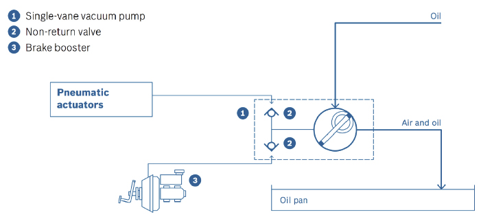
Most modern VWs use either an electric vacuum pump or a pump driven by a sprocket connected to the timing chain. These pumps use vanes attached to an offset shaft. As the shaft rotates, the vanes create a sealed chamber with the walls of the housing.
Since the shaft is offset, the chambers change in volume and produce a vacuum on the outlet side when turned. Electric pumps typically have multiple vanes; timing chain-powered pumps use just one vane.
Electric-powered vacuum pumps are controlled by the engine control module. The system uses a pressure sensor mounted between the pump and the booster. The ECM will look at the vacuum, brake pedal position and other engine parameters. The vacuum pump is controlled with a relay that is actuated by the engine control module. The pump is turned on for 2- to 3-seconds during startup.
Timing chain-powered pumps are lubricated with engine oil. The oil inlet is next to the shaft and is fed from the oil slung off the timing chain and sucked into the pump through a valve that controls the level of oil.
While it is rare for the vanes to wear out, it is possible for carbon and debris to enter the pump and cause damage to the vanes and housing. If the vanes can’t seal against the housing, a vacuum can’t be generated. The most common symptom of a worn pump is a hard brake pedal.
The Booster
No matter if the booster gets vacuum from the engine or a pump, if it is damaged, the brake pedal performance will change. The condition of the diaphragm inside the booster is also important. If it’s cracked, ruptured or leaking, it won’t hold vacuum and can’t provide much power assist. Leaks in the master cylinder can allow brake fluid to be siphoned into the booster, accelerating the demise of the diaphragm.
If there’s brake fluid inside the vacuum hose, it’s a good indication that the master cylinder is leaking and needs to be rebuilt or replaced. Wetness around the back of the master cylinder would be another clue for this kind of problem.
To check the vacuum booster, pump the brake pedal with the engine off until you’ve bled off all the vacuum from the unit. Then, hold the pedal down and start the engine. You should feel the pedal depress slightly as engine vacuum enters the booster and pulls on the diaphragm. No change? Then check the vacuum hose connection and engine vacuum. If it’s OK, the problem is in the booster, which needs to be replaced.
Continental Multi-V belts are designed for OE-quality performance in both domestic and import applications. Learn about the different belt technologies, including Elast stretch belts, Extra belts for hybrid vehicles, and dual-sided belts for specialized accessory drives.
This video is sponsored by Continental Belts and Hose.
The post Continental Metric Belt for Import Applications appeared first on Brake & Front End.
Jika Anda ingin bermain slot online di server Thailand, penting untuk memahami berbagai istilah yang digunakan dalam permainan. Dengan memahami istilah-istilah ini, Anda bisa lebih mudah memilih permainan yang tepat, mengoptimalkan strategi, dan meningkatkan peluang kemenangan.
🔹 1. Istilah Dasar dalam Slot
Istilah
Penjelasan
Spin
Putaran gulungan dalam permainan slot.
Payline
Garis pembayaran tempat simbol harus sejajar agar menang.
Reel (Gulungan)
Kolom vertikal tempat simbol muncul dalam slot.
Row (Baris)
Baris horizontal yang membentuk kombinasi slot.
Balance (Saldo)
Jumlah uang yang tersedia untuk bertaruh.
Bet (Taruhan)
Jumlah uang yang dipertaruhkan per spin.
Win (Menang)
Jumlah uang yang didapat setelah menang dalam satu spin.
📌 Tips: ✅ Pilih slot dengan banyak paylines untuk lebih banyak peluang menang. ✅ Sesuaikan taruhan dengan saldo agar bisa bermain lebih lama.
🔹 2. Istilah Terkait Fitur Bonus
Istilah
Penjelasan
Wild
Simbol yang bisa menggantikan simbol lain untuk membentuk kombinasi menang.
Scatter
Simbol yang memicu fitur Free Spins atau Bonus Game tanpa harus sejajar di paylines.
Free Spins
Putaran gratis tanpa mengurangi saldo taruhan.
Multiplier
Pengganda kemenangan (misal x2, x5, x100).
Bonus Game
Mode permainan khusus dengan hadiah tambahan, sering diaktifkan oleh Scatter.
Sticky Wild
Wild yang tetap di tempatnya selama beberapa putaran.
Expanding Wild
Wild yang meluas ke seluruh gulungan untuk meningkatkan peluang menang.
📌 Tips: ✅ Cari slot dengan fitur Free Spins & Multiplier besar untuk menang lebih banyak. ✅ Perhatikan kapan Scatter muncul untuk memanfaatkan fitur bonus.
🔹 3. Istilah Terkait RTP, Volatilitas, dan Pola Slot
Istilah
Penjelasan
RTP (Return to Player)
Persentase pengembalian ke pemain dalam jangka panjang. RTP tinggi (96%+) lebih menguntungkan.
Volatilitas
Menentukan seberapa sering slot membayar dan seberapa besar hadiahnya.
High Volatility
Kemenangan besar tapi jarang. Cocok untuk pemain yang sabar dan punya modal besar.
Low Volatility
Kemenangan kecil tapi sering. Cocok untuk pemula atau pemain dengan modal kecil.
Hit Rate (Frekuensi Kemenangan)
Seberapa sering slot memberikan kemenangan dibandingkan jumlah total spin.
📌 Tips: ✅ Jika ingin menang cepat, pilih slot volatilitas rendah dengan RTP tinggi. ✅ Jika mengejar jackpot besar, pilih slot volatilitas tinggi seperti Gates of Olympus.
🔹 4. Istilah Terkait Mode Bermain
Istilah
Penjelasan
Auto Spin
Mode otomatis untuk menjalankan spin tanpa menekan tombol setiap kali.
Turbo Mode
Mode mempercepat animasi spin untuk hasil lebih cepat.
Demo Mode
Mode bermain gratis tanpa uang asli, cocok untuk latihan.
Max Bet
Taruhan maksimum dalam satu spin untuk peluang menang terbesar.
Min Bet
Taruhan minimum dalam satu spin untuk bermain lebih lama.
📌 Tips: ✅ Gunakan Demo Mode sebelum bermain uang asli untuk memahami pola slot. ✅ Jika saldo terbatas, hindari Max Bet agar bisa bermain lebih lama.
🔹 5. Istilah Terkait Jackpot & Bonus Tambahan
Istilah
Penjelasan
Jackpot
Hadiah terbesar dalam permainan slot.
Progressive Jackpot
Jackpot yang terus bertambah hingga ada pemain yang menang.
Fixed Jackpot
Jackpot dengan nilai tetap, tidak berubah seiring waktu.
Respin
Fitur yang memungkinkan pemain memutar ulang gulungan tertentu tanpa biaya tambahan.
Tumble Feature (Cascading Reels)
Simbol pemenang hilang dan digantikan oleh simbol baru dalam satu putaran, bisa memicu kemenangan beruntun.
📌 Tips: ✅ Pilih slot dengan Jackpot Progresif jika ingin peluang menang besar. ✅ Gunakan Cascading Reels untuk mendapatkan kemenangan berturut-turut dalam satu spin.
🎯 Kesimpulan: Menguasai Istilah Slot untuk Menang Lebih Banyak
Memahami istilah-istilah dalam permainan slot di server Thailand bisa membantu Anda memilih game terbaik, mengatur strategi, dan memaksimalkan kemenangan.
🔥 Rekomendasi: ✔️ Pilih slot dengan RTP tinggi (96%+) dan volatilitas sesuai gaya bermain Anda. ✔️ Manfaatkan fitur Wild, Scatter, Free Spins, dan Multiplier untuk peluang menang lebih besar. ✔️ Gunakan Demo Mode untuk latihan sebelum bermain dengan uang asli.
Dengan pemahaman yang lebih baik, Anda bisa bermain lebih cerdas dan meningkatkan peluang menang!
Electric power steering (EPS) or electric power assisted steering (EPAS) systems continue to rise in popularity among auto makers. Diagnosing these systems can be a challenge. There are a few different types of EPS systems. Some mount the motors onto the steering column, on the pinion shaft against the steering rack, or on a secondary pinion gear on the other side of the steering rack. Despite their differences, they all operate with the same goal: assisting the driver whenever turning the steering wheel.
Letâs take a closer look at the sensors which make up these systems, and how they operate.
The Big Picture
EPS systems apply steering assist force based only on driver input. The system uses input data from a multitude of vehicle sensors to determine how much steering assist force is required. More often than not, the problem ends up being a faulty sensor, wire, or connection somewhere in the system.
The EPS system is connected to the powertrain CAN-BUS, and communicates with a number of systems. Figure 1 shows the powertrain CAN-BUS on a late-model Volkswagen. You can see that the EPS control unit is just one part of the network of sensors and control units.
Figure 1
This connectivity has some serious advantages. The EPS module isnât connected directly to the wheel speed sensors, but the ABS control unit is able to pass that data along on the BUS. Itâs important to understand just how interconnected systems can be on modern vehicles.
Steering Angle Sensor
The steering angle sensor is arguably the most important sensor in the system; thatâs why itâs first on the list. It is located between the steering column and the wheel, and, in many cases, is actually one part of a sensor cluster. This is due to the importance of the data it produces. A faulty steering angle sensor reading could mean the difference between making it around a corner, or colliding with another vehicle. Having multiple sensors onboard to measure the same thing offers built-in redundancy, and allows the control unit to confirm the data in real time.
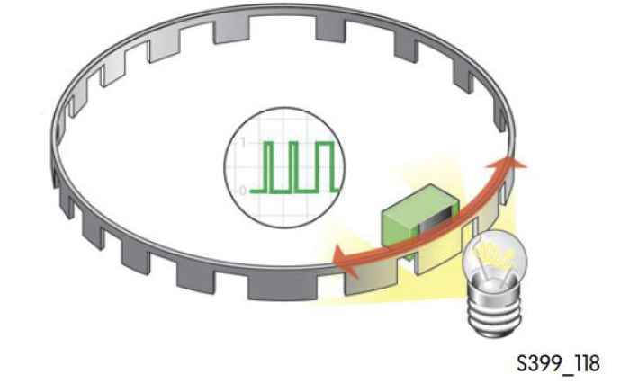
Sensor operation will vary from one manufacturer to the next, so itâs best practice to always check the OEM service information before you start with diagnosis. Letâs look at a 2019 VW Golf Alltrack as an example. The sensor consists of two rings: the absolute (outer) ring, and the incremental (inner) ring. Each ring is divided into segments, which are read by a light barrier set (Figure 2).
Figure 2
When looking at the data PIDs, you should see at least one steering angle sensor reading, measured in degrees. Sweep the steering wheel back and forth to confirm that the sensor is reading the change.
Steering Torque/Force Sensor
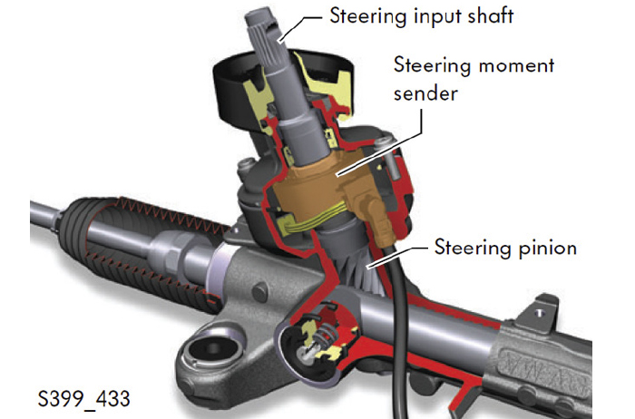
The second sensor on our list is the steering force sensor, also known as the steering torque sensor or steering moment sensor. This sensor is typically mounted on or inside the steering rack, and connected to the pinion gear (Figure 3). It is used to measure the amount of steering force that is being applied by the driver, then the control unit calculates how much steering assist force is needed, and applies it using the electric motor.
figure 3
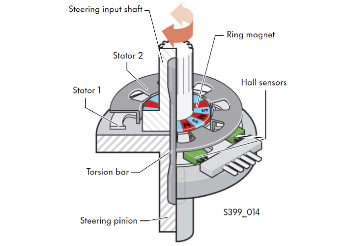
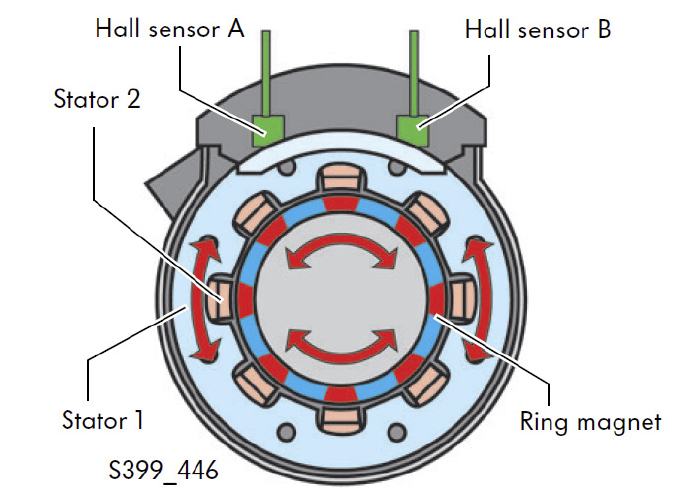
Again, sensor operation will vary from one manufacturer to the next, but weâll use the 2019 VW Golf Alltrack again as an example. The steering input shaft and the pinion are connected by a torsion bar. A magnetic ring is affixed to the input shaft, and stators are affixed to the pinion (Figure 4). As the input shaft rotates, the torsion bar will twist, and the magnetic ring will move in relation to the stators (Figure 5). As a magnetic field is formed, the linear Hall sensors measure the electrical signal and calculate the amount of force being applied.
Figure 4
Figure 5
When looking at the data PIDs, youâll likely see two separate force/torque readings, measured in lb.-ft. or Nm. Turning the steering should cause these PIDs to rise.
Other Sensors
The EPS control unit monitors a number of additional sensors to ensure that the system operates efficiently, and doesnât overheat. This includes, but is not limited to, the speed and power draw of the electric motor, the temperature of the control unit and electric motor, wheel speed, and the engine speed. All of these PIDs and more can be monitored by a scan tool, and can be invaluable when it comes time to diagnose an EPS system which is misbehaving.
Tips & Tricks
Needless to say, youâll need a scan tool capable of bi-directional control for this type of work, a simple code reader wonât cut it here. Youâll need to scan the system for stored DTCs, then bring up the real-time data (PIDs) from the onboard sensors.
Check the OEM service information to see if there is updated software for the modules; this may clear up the customer concern. Youâll also want to familiarize yourself with how each of the sensors work on that particular application. Pay close attention to any service bulletins or notes from the manufacturer. This can save you (and your customer) some serious headaches!
The steering angle sensor needs to be reset or recalibrated whenever the battery has been disconnected, an alignment has been performed or the steering wheel has been removed. Be sure to get the wheels pointed straight ahead after an alignment is performed. If this isnât done right, the system can be led to believe that the vehicle is drifting out of the lane, and could try to make an unnecessary correction. Follow the OEM service procedures to the letter, as failing to properly calibrate the sensors could lead to trouble down the road.
To understand why using the correct transmission fluid is necessary, you first have to know how the transmission fluid flows inside an automatic transmission.
Fluid Paths
The journey starts in the pan. The transmission fluid is drawn from the pan through a filter by the pump that is behind the torque converter. The fluid level in the pan and transmission body is critical. Too little, and the transmission will suck air into the pump. Too much transmission fluid and the fluid will come in contact with the rotating components. Both scenarios lead to aeration of the transmission fluid.
First off, air or bubbles in the transmission fluid can be bad for the performance of the transmission because air can be compressed; fluid can’t be compressed. Air in the system can prevent solenoids, check valves and actuators from engaging clutch packs and bands on the drums. It can even prevent the torque converter from engaging the transmission and shifting the gears. This is basic hydraulics.
The pump first generates a suction force that draws the fluid into the chamber and is eventually compressed on the other side with considerable pressure. Some transmissions might have a second pump in the rear. The pressure created can cause cavitation that can introduce tiny bubbles into the fluid if the formulation is incorrect or the additive package is worn out.
After the pump comes a valve or valves that do two things. First, it controls line pressure to the valve body and other components. On most transmissions, the line pressure must remain constant as input and output speeds change and as solenoids open and close. To keep the correct line pressure, the fluid must have the correct weight or viscosity.
Second, the pressure regulator valve will direct the fluid to the components like the valve body, torque converter, gears and servos. It will also direct some fluid into a thermostatically controlled cooler circuit.
For most transmissions, the first stop after the pressure regulator is the torque converter. For the torque converter to work, the stator, turbine and impeller must be submerged in fluid. If air exists inside the body of the torque converter, the fluid can become aerated or foamy, the efficiency of the turbine and impeller is compromised and the vehicle might not move.
On most late-model transmissions, the fluid inside the torque converter lubricates the friction materials and surfaces of the clutch that control lockup. In addition, fluid travels through the turbine and output shaft to lubricate clutch packs, shafts and planetary gears.
The pressure regulator valve also supplies consistent line pressure to the valve body. The valve body is nothing more than a series of valves, solenoids and accumulators that are connected to servos that engage clutch packs and bands that control that controls the planetary and sun gears of the transmission.
Fluid Conditionals
Hydraulic components need clean fluid that is of the correct viscosity to control the input and output of the transmission. If the fluid is not correct or worn out, it can cause the valves to leak or stick, and cause slipping or even harsh shifts.
Transmission fluid may stay in passages of the valve body and servos and eventually be cycled through relief ports. Some circuits in the turbine and output shaft carry heat away and lubricate friction surfaces. But, it will ultimately end up in the pan, and the fluid will be cycled through the transmission again and again.
Keep in mind, a transmission is a sealed system. What contaminates transmission fluid is high temperatures that oxidize the fluid and break down the raw ingredients. This eventually leads to damage of the components inside the transmission.
Now that we know the flow of the transmission fluid, we can understand what the fluid is up against inside the case of the transmission.
There is not a single or universal recipe for automatic transmission fluid. Most fluids use the same type of ingredients, but they are formulated to different specifications depending on the transmission manufacturer.
The transmission fluid is formulated for the friction material used on the clutches, gasket and seal materials, the metallurgy inside the transmission, the length of the service interval, fuel economy requirements, shift quality, and performance at specific temperature ranges.
The engineers at the OEMs and fluid formulators have many ingredients to choose from to achieve the desired performance.
By volume, the number one ingredient is the “base stock.” This is a highly refined mineral oil classified as a synthetic fluid. The base stock is formulated for performance under high and low temperatures, shear strength and other lubricating properties. It represents 80 to 90 percent of the volume of the fluid.
The viscosity specification of the base stock is going lower on the latest transmissions to improve the pump’s efficiency. This is why you see transmission fluid bottles and specifications with “LV” or low viscosity in their names.
Additive Packages
The other ingredients in transmission fluids represent its additive package. These chemical ingredients help to give the transmission fluid the ability to operate and protect the transmission.
By volume, detergents are the next largest ingredient in transmission fluid. Detergents help keep surfaces clean from varnish, an advanced form of sludge, and act as dispersants to control contamination and sludge.
When transmission fluid is exposed to extreme temperatures, the long chemical chains of the hydrocarbon base stock are damaged when they bond with oxygen. So, instead of a nice long chain, they look like balls of wadded-up molecules that can be very sticky. These oxidized molecules like to stick together because they are electrically charged. As more fluid is oxidized, more of them can stick together and form sludge and varnish.
Detergents and dispersants surround oxidized particles and prevent them from linking up and forming sludge and varnish. The contamination remains suspended in a solution with a protective layer around it.
To prevent the transmission fluid from oxidizing, transmission fluids will include antioxidants. These chemicals enhance thermal stability, improve lubricant performance and reduce sludge formation. They also minimize fluid thickening and control acid formation.
Fluid and Friction
Friction modifiers control the friction levels between the components of the clutches and bands. These ingredients can be tuned to give the best shift performance and extend the longevity of the friction materials.
Anti-wear ingredients are designed to reduce wear between the metal parts that are under extreme pressure. These chemicals help improve the lubricity of the fluid, so it sticks to a metal surface.
Another part of the additive package are anti-foaming ingredients that prevent bubbles from forming in the fluid. Bubbles can be formed due to cavitation in the pump, torque converter and the actuation of the valves since air is compressible. Foamy fluid can change shift characteristics and the hydraulic operation of the transmission.
There are also buffers that control the pH of the fluid. They help to reduce corrosion inside the transmission.
The base stock and additive package must be compatible with the metals, gaskets and seals inside the transmission. Some transmission fluids even include seal conditioners to keep gaskets and seals flexible.
The additive package components do degrade or become depleted over time and need to be replaced by installing fresh transmission fluid. In other words, the chemicals that control the pH friction levels and prevent sludging have a limited supply. When these ingredients are exhausted, their control over the characteristics of the fluid quickly changes.
Most ADAS system features and their performance are a mystery to the vehicle’s owner and even the dealership. Often a normal activation of the system is misunderstood, which creates problems for the person trying to address a customer complaint. But, what can be worse is trying to figure out why an ADAS feature did not activate.
With today’s modern ADAS systems it can be difficult to determine what is normal and what is a false activation from just a customer complaint. Over the past two decades, ABS, ESC and ADAS have changed the driving experience. When an average driver started driving, they had brake and chassis systems that alerted drivers to potential safety risks with mechanical cues like locking brakes, oversteer and understeer. The first significant change came with ABS. If you were working 25 years ago, you would expect to get customers complaining about sinking and pulsating brake pedals on the first snow of the year.
Many of these complaints are routine operations for the system. But, there is always the possibility of a false activation of these systems when a correction is not required. Diagnosing false activation of a safety system like ABS or automatic emergency braking (AEB) can be difficult due to the intermittent nature of the complaint. Many false activation scenarios focused on a single malfunctioning sensor, but with ADAS, the cause of false activation of a feature could be more mechanically holistic.
One of the first false activation complaints was ABS activation at speeds between 3 and 15 mph. This problem usually starts with the wheel speed sensors. A weak signal from a sensor is interpreted as a locked wheel, which triggers the computer to activate the ABS and release brake pressure to unlock the wheel. The driver might experience a longer-than-normal stop. The cure for false activation is to clean the tip of the wheel speed sensor, inspect the tone ring and adjust the air gap. This typically fixes the problem.
New magneto-resistive or “active” wheel speed sensors are not prone to issues of metal accumulation on the tip of the sensor. However, debris can build up on the magnets embedded in the reluctor ring in the outer seal of some sensors. This can take a long time to accumulate.
False activations are still a problem with active sensors, but more advanced modules can determine if a wheel is locked or has a wheel speed sensor problem. Instead of activating the ABS module and causing long stops, the system will deactivate and the ABS warning light will turn on.
ESC FALSE-ACTIVATIONS
The next false-activation scenario involves the ESC system. The source of the problem can be more than one sensor and can even be traced to alignment angles. The customer may overlook an issue until there is a mechanical problem with the brakes. In these cases, you may notice that one wheel is covered in brake dust. Some customers may complain that the ESC activates on slower corners or on highway off-ramps.
The most important sensor is the steering angle sensor, which measures the steering angle, steering wheel speed and torque the driver applies. This input tells the ESC system what the driver wants to do. The other sensors tell the ESC system what the vehicle is doing.
Let’s examine what happens during an understeer condition where the wheel turns, but the vehicle travels in a straight line. The driver will continue increasing the steering angle, but the lack of traction keeps the vehicle straight.
The ESC computer sees the understeer event via the sensors long before the driver realizes it. The ESC computer also sees that the driver’s steering angle is greater than the actual path measured by the yaw and lateral accelerometers.
The ESC system intervenes to make the vehicle turn using the brakes. The first action might be to close the throttle to transfer weight to the front so the tires can gain traction. The next action might be to increase braking force on the inside front and/or outside rear tire to get the vehicle to rotate. All this time, the sensors are monitoring what the driver is doing and the effectiveness of the correction. This happens in nanoseconds.
Let’s say a steering position sensor gives a false reading of an extra 50° when the car travels in a straight line. The ESC might perform a correction by activating the brakes to get the steering angle to match what the other sensors are seeing.
The other possibility is the extra 50° on an off-ramp may trigger the ESC system because it is interpreting the signals as an understeer condition.
Another false activation scenario can be caused by an excessive thrust angle. The thrust angle is an imaginary line drawn perpendicular to the rear axle’s centerline. It compares the direction the rear axle is aimed at with the vehicle’s centerline. Excessive thrust angle can cause the vehicle to go down the road at an angle with the steering wheel turned to one side.
The ESC system can experience the effects of an excessive thrust angle but can’t see the thrust angle. The yaw sensor shows that the vehicle is not traveling in a straight line, and the accelerometers and the steering angle indicate that the driver might be trying to correct it. The accelerometers tell the system that nothing is happening.
The ESC system might read this as the rear end starting to step out, which could be interpreted as an oversteer. The ESC system might try to correct the condition by pulsing the inside rear brake.
ADAS False Activations
ABS and ESC systems are essentially blind. They can sense what is occurring with vehicle dynamics and interpret the driver’s inputs. ADAS systems can sense what is happening outside the vehicle, like lane markings and other objects around the vehicle. ADAS does this using cameras, lasers and radar. The three systems control the vehicle’s dynamics and calculate an effective correction for the circumstances and environment.
False activations can range from the automatic braking system stopping a vehicle when pulling out of a garage, to activating a lane-keeping system when the customer does not expect a warning or even steering correction. The secret to resolving these complaints is to treat them like a drivability problem with a condition, cause and correction.
The condition caused by an ADAS activation might be completely normal. The correction might be a warning or the activation of the brakes or steering. The key to understanding the condition is to know the criteria for activation of the system.
Many ADAS functions and corrections operate with a similar strategy as an emissions monitor. Like an oxygen sensor or misfire monitor, specific criteria and number of events must be met for the system to activate.
The other keys to know are the ADAS outputs during a dangerous situation. For some early systems, it was just an audio or visual alert. Some newer systems will shake the driver’s seat to alert the driver. More advanced systems can build up brake pressure and apply the brakes if a collision is imminent. Some systems will take further steps with the steering and even close the windows.
Many ADAS features do not become active until the vehicle reaches a specific speed. Depending on the OEM, pre-collision systems might start working between 5 and 10 mph. Lane departure might not begin to work until the vehicle is traveling above 25 mph. The takeaway from this is that a test drive is required after calibration is performed. Simply pulling out of the bay and parking the vehicle in a spot will not allow the vehicle to activate or run a self-diagnosis routine. Knowing the speed range limits of these systems is critical if you try to perform a dynamic calibration on the road.
The logic behind most ADAS warnings or corrections is to examine the plausibility of the situation. For example, if the camera classifies an object as another vehicle, it will also use the radar sensor to confirm the vehicle’s path. If only one sensor detects an object, it might just decide the camera has made a false identification, and the plausibility that it is another vehicle is low.
Before you start a calibration procedure, you need to prepare the vehicle. Missing a step can cause the calibration process to be aborted or calibration to be off. Also be aware that something as simple as a weak battery can cause problems.
Inspecting the sensors and the vehicle for damage is the first step. Damage to the short- and long-range sensor behind the bumper covers or front air dam might not be seen during the initial inspection, but minor collisions can disturb the sensor and damage the mounting points. It could be from hitting a snowbank or parking block.
You might have to remove the bumper cover to inspect the sensor. The most common symptom is false or delayed activation of the system. If the front radar sensor is pointed up or down, it might detect another vehicle too late, and the correction might be more severe than expected. If the sensor is pointed too far left, it could think it is oncoming traffic in the vehicle’s path.
The other key inspection point is to look at the dash for any lights or messages. Never assume a check engine light is only for engine issues; many codes indicate a loss of communication with the different modules on the vehicle. ADAS systems communicate with many modules on the vehicle. Any problems with missing data could cause problems for ADAS calibrations. If the light is on, pull all the codes from the modules.
An alignment should also be performed to ensure the thrust line is within specifications. The steering angle sensor should also be reset as part of the alignment. Failing to reset the sensor might cause a steering pull and issues with the electric power steering system. It could also make the vehicle think a vehicle in the opposing lane is coming right at them. On some vehicles, the driver may get a warning or correction.
A brake rotor absorbs and dissipates the heat energy generated by friction. How well the rotor can absorb and then release it into the surrounding air will determine the efficiency and capacity of the brakes.
The design of the rotor determines how it can handle the heat. On vented rotors, the thickness of the plates and how well air flows through the vanes helps to transfer heat to the surrounding air. Curved-vane designs on some vented rotors help to pull air through the center of the rotor to the outer edge and act as a pump. For curved vanes to work, they must be mounted on the hub in the correct direction, just as a directional tire must be mounted on the right wheel.
Slots cut into the face of the rotor have two functions. First, they provide leading edges for a better initial bite from the pad. Second, each groove provides a path for the gases being released by the pad. If the slots fill up with pad material, the brake system is operating at too high a temperature. Slots are radiused when milled to prevent stress in the rotor. Most slotted rotor manufacturers will not cut the slot to the edges of the rotor; doing so will compromise the strength of the rotor.
Holes drilled in the rotor can provide another path for the gases to escape from the pads and help with the initial bite of the pad. In some cases, the holes can reduce the weight of the rotor and improve cooling, as well. But there is a science to the holes, so the structure of the rotor is not compromised. Too many holes or holes near vanes can cause cracks. Also, the hole should have a chamfer to avoid creating a stress riser that can cause a crack.
The size of the brake rotor determines the rotor’s ability to generate brake force or torque. The best analogy is to try to turn a steering wheel using an inner spoke and then again using the outer wheel portion. The farther you move your hand out, the easier it is to turn the wheel.
Two-piece rotors included on some cars and in “big brake” kits have two advantages. First, two-piece rotors reduce rotational and unsprung mass. Second, the hat that is made of aluminum acts as a heat dam to prevent heat from being transferred to the hub, bearings and knuckle.
The most significant trend in rotors is using slots, holes and finishes on the hat and vanes to improve the cosmetics of the brake system.
While some of the aspects of Advanced Driver Assistance Systems – or ADAS – still seem like cutting edge technology found only in the world’s most advanced vehicles, the truth is that some of these systems have been around for decades, giving the promise of safer driving experiences to drivers all over the world.
Unfortunately, even though modern vehicles are equipped with increasingly advanced electronic safety systems, traffic fatalities have been on the rise since 2014, and while distracted driving may be a factor, we know that electronic safety systems are not able to offer the benefits they are capable of when vehicles are not maintained.
The performance of electronic safety systems is dependent on more components than you may realize. ABS wheel speed sensors and steering angle sensors provide real-time data that electronic safety systems depend on. ADAS related components like these from Standard are precision engineered and manufactured, and they’re also tested on real vehicles to ensure that they integrate seamlessly with the complex safety systems found in today’s modern cars.
Standard’s Collision Repair Program includes more than 8,000 of the hard-to-find, yet easily damaged parts that collision shops and repair facilities are looking for, including more than 900 ADAS-related components, such as park assist cameras, lane departure system cameras, and advanced sensors like blind spot detection sensors, cruise control, distance sensors, and park assist and steering angle sensors.
It’s the correct integration to the vehicle’s system that is so critical, so be sure your customers and your technicians understand programming and calibration requirements. For example, components like lane departure system cameras will generally require calibration after an installation but some components such as park assist sensors can just be installed on many vehicles without any programming necessary. So, if an ADAS component doesn’t seem to work correctly initially , it’s unlikely it’s a bad part. If you don’t perform the necessary calibration, the part isn’t defective, the installation was just never correctly completed.
Before replacing any ADAS component, it is important to refer to specific service information for the procedures required for that component. And before installing any replacement part after a collision, make certain that the mounting surface is true to the original location.
To ensure a complete and timely collision repair, Standard offers a wide range of award-winning in-person, live virtual and online learning classes to better educate technicians. You can do the work for your customer with the right parts and training from Standard.